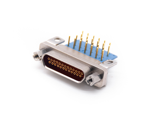
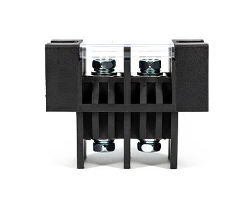
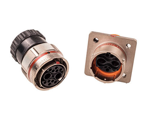
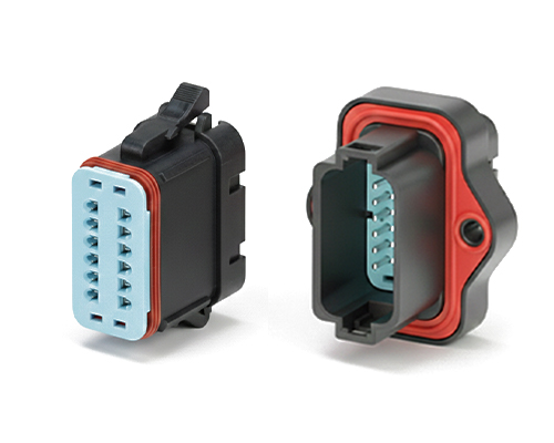
The Rectangular Connector is widely used in aerospace, medical instruments, consumer electronics (such as computers, TVs, game consoles, etc.), industrial control equipment, communication equipment, and automotive electronics. With its reliable connection performance, diverse specifications, and relatively convenient plug-in and unplug operations, it has become an indispensable component in various electronic and electrical applications.
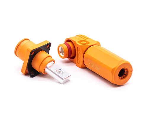
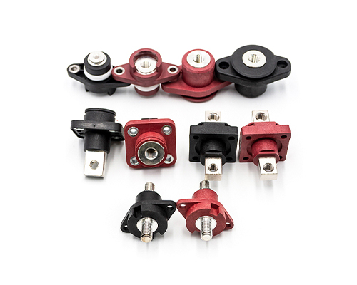
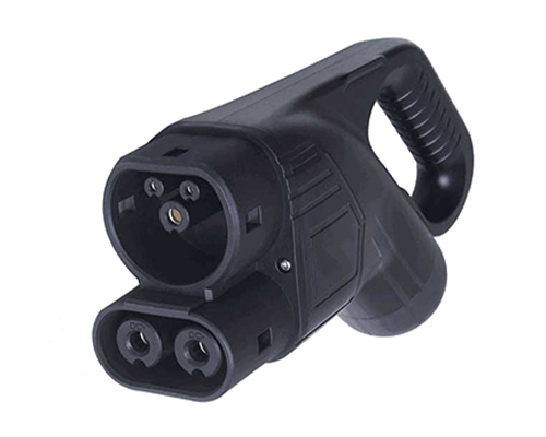
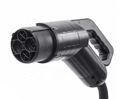
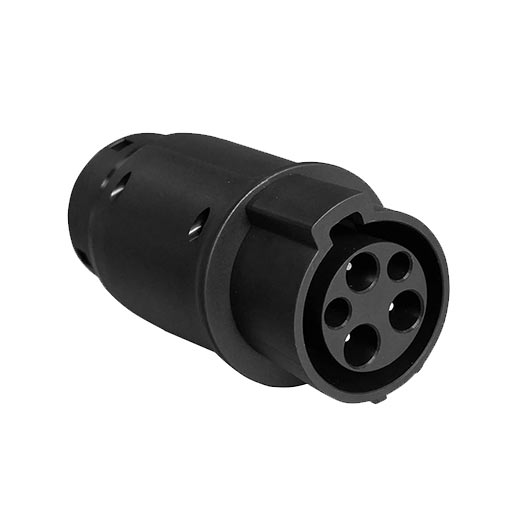
High Voltage Connectors are widely used in EV power systems, renewable energy installations, and industrial high-voltage circuits. Renhotec’s series drives the building of efficient, safe, and sustainable electrical ecosystems, meeting current technological demands.
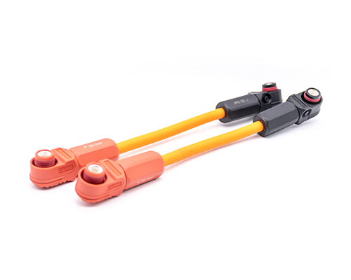
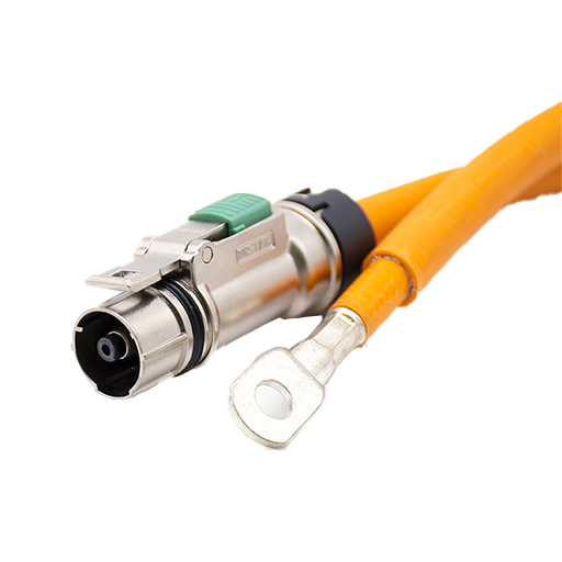
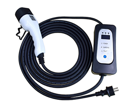
Renhotec EV Cable, crafted with top-notch conductive materials and meticulously engineered insulation, showcases outstanding impedance control and voltage-withstanding properties. Its design combines flexibility and durability to meet a wide array of installation needs. This cable is widely utilized in grid interconnections, large-scale industrial power supply systems, and high-voltage renewable energy projects, enabling smooth and efficient power transmission.
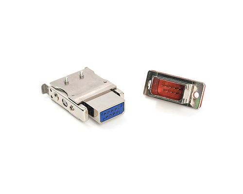
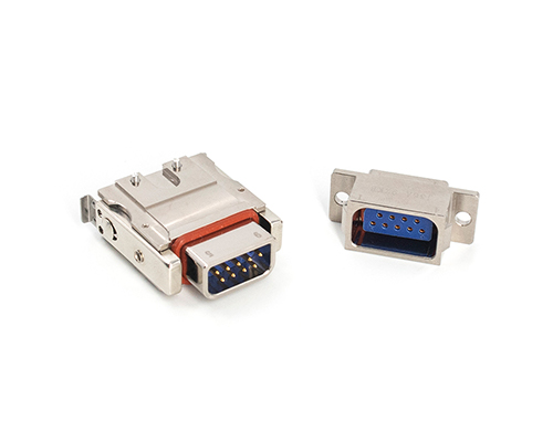
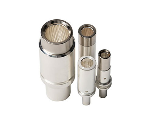
Renhotec, as a professional supplier, offers a comprehensive range of these Signal Transmission Connector products. Whether it is the high-reliability applications of the metal series or the wide adaptability of the plastic series in consumer electronic products, Renhotec can provide customers with high-quality options to meet the diverse requirements of signal transmission connections in different industries and scenarios.
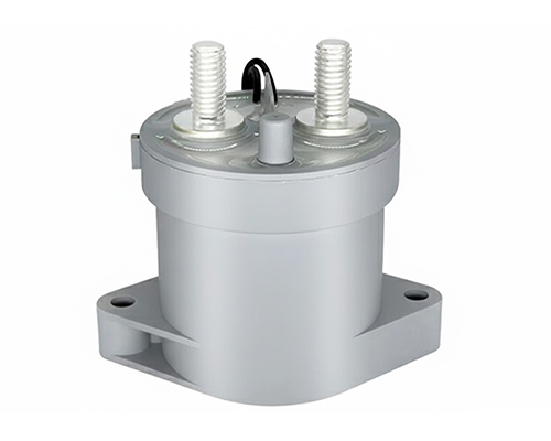
Renhotec, active in electrical components, offers High Voltage DC Contactors in Epoxy Resin Sealing and Ceramic Sealing variants, with a 20A – 1000A current range. The Epoxy Resin Sealing one is cost-effective and protective. The Ceramic Sealing variant excels in thermal stability and insulation. They’re widely used in EV charging, renewable energy grid, and industrial high-voltage DC power distribution for reliable circuit control and current interruption, providing comprehensive solutions for multiple sectors.
Analysis of High Voltage Connector Technology and Design
The steady development of the new energy vehicle industry has led to the continued development of automotive connectors, especially high-voltage connectors. But, in recent years, North America, Europe, and Japan’s connector market growth have been slow due to the impact of global economic fluctuations. In contrast, China, the representative of the emerging markets, shows continued growth momentum, becoming the main driving force behind the growth of the global connector market.
To this end, the world’s leading connector companies have moved their production bases to the country. Including TE Connectivity, Molex, Delphi, etc., continue to invest in domestic factories. China has become the world’s largest connector production base, especially in the government’s policy to promote incentives. China’s new energy automotive industry has led to the steady development of automotive connectors continue to develop.
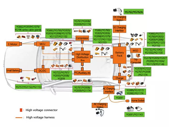
Application of high voltage connectors in complete vehicle systems
New energy automotive connector is one of the connector categories for the development of new energy vehicles in recent years. Gradually changing from the traditional high-voltage, high-current and low-voltage automotive connectors to a separate class of connectors. Compared with the traditional high-voltage, high-current connectors. New energy vehicle connectors are more complex, and variable working conditions, the reliability of the connector requirements are higher.
Compared to the traditional low-voltage automotive connectors. Due to the increase in voltage level (the current mainstream system voltage is higher than 300V DC), increasing the risk of injury to the human body by electric shock, the connector’s safety requirements are higher. Therefore, the insulation and protection requirements of the product are higher than those of traditional low-voltage plug-ins.
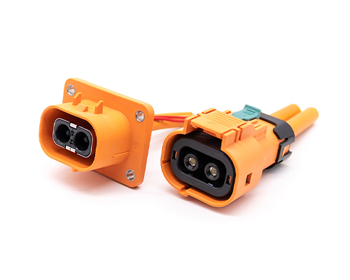
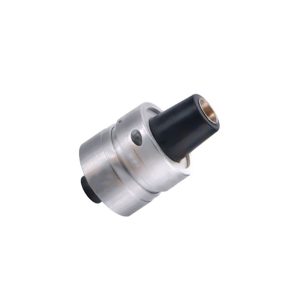
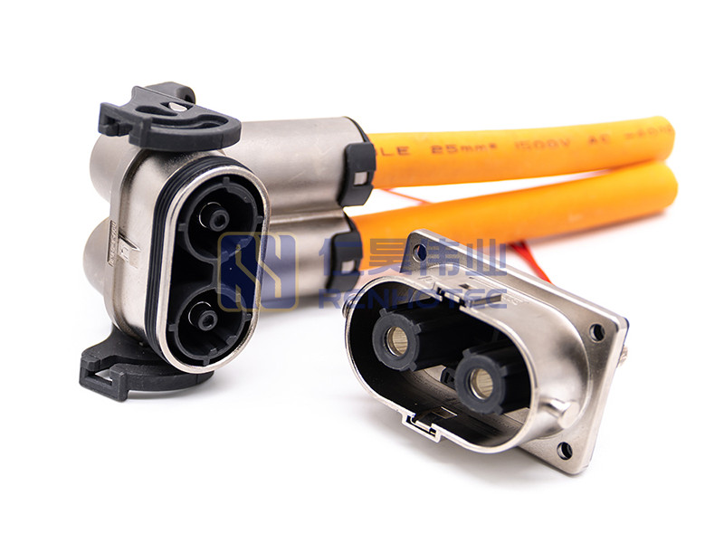
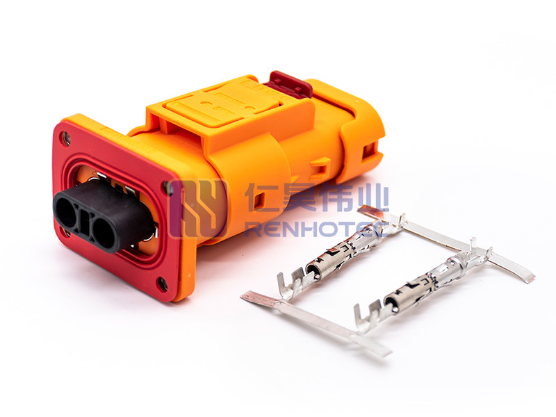
The role of the new energy vehicle connector is mainly to ensure that the entire vehicle’s high-voltage interconnection system. That is, bridging the internal circuit where it does not work so that the current flows. The new energy vehicle connector generally consists of three parts: the shell, the seal and other auxiliary structures, the insulating part, and the pair of conductive contacts.
You can achieve the function of connection and conductivity through the plug sheath and socket sheath between the plug mutual cooperation. High voltage connectors mainly apply to high voltage high current circuits and conductive cables for new energy vehicles. The battery pack energy through different electrical circuits, transported to the vehicle system components. Such as battery packs, motor controllers, DCDC converters, chargers, and other body electric units.
A layout of a high-voltage connector used in a complete vehicle system
Analysis of Key Items of High Voltage Connector Design
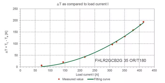
1. Temperature rise and derating curve value
Temperature rise is one of the most important design key items in the connector design; abnormal temperature rise will lead to the connector because of high-temperature rise, the occurrence of ablation.
The temperature rise of the connector is affected by the following factors.
(1) Contact resistance:
The resistance between the two contact carriers for conductive connections. Such as pinhole-to-plug contact resistance, pinhole tail, wire crimping resistance, and the threaded connection between the copper plate and the contact resistance.
(2) Material environment heating:
When the product is used in an environment where the temperature is too high. Due to its internal contact resistance, the connector heats in reaching thermal equilibrium, plus the ambient temperature. Which is higher than the maximum working temperature of the material allowed to use.
If the connector is in an environment for a long time, the internal pinhole parts’ heat caused by the internal temperature can not be discharged. The internal temperature will continue to rise. The connector will generate a lot of heat, resulting in the ablation of the connector caused by vehicle combustion. Rubber and metal materials have a maximum working temperature limit. They will need to take them into account when designing.
(3) The connection of the plate end:
The case design uses bolts or precautions to prevent the supply of loose. Simultaneously, the bolt connection must be based on the operating specifications for torque testing. Conductive parts screw connection case, one of the main failure modes, is not following the torque requirements for tightening torque control, resulting in abnormal temperature rise and ablation of the connection parts.
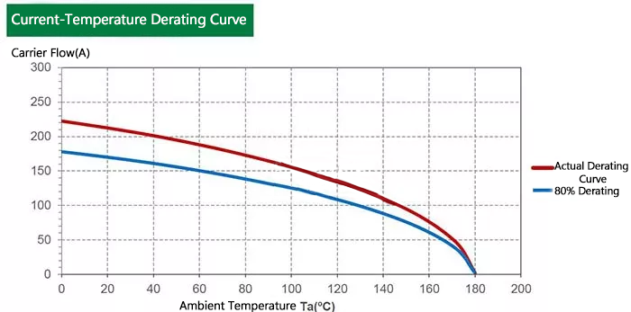
(4) Derating curve:
A derating graph is like when you go to select a commodity that you want to use in a specific environment. Then choose the commodity when you have to determine which interval range you choose based on the value of a property of this commodity.
A high-voltage connector derating curve provides customers with a menu. According to this menu, customers correspond to their tastes to choose their appropriate dishes.
Derating curves are different currents in different operating environments corresponding to different temperature values. These values are through the tracing point method to get a graph. And with this derating curve can be more intuitive to see the conditions of use of the connector.
Temperature Rise Curve Values
Temperature Derating Curve Values
2. High voltage interlocking (HVIL)
For the entire high-voltage interconnection system, the connection design incorporates the concept of high-voltage interlocking to ensure the safety of the high-voltage system up and down. It is described as that when the connector is inserted, it first contacts the high-voltage circuit, and then turns on the high-voltage interlock signal circuit. When disconnecting, first disconnect the high-voltage interlock signal, and then disconnect the high-voltage circuit.
Most connector manufacturers will put the high-voltage interlock design inside the connector; some will put the high-voltage interlock through the auxiliary structure design outside the plug cavity. It is important to ensure the stability of the high-voltage interlock circuit. Suppose the high-voltage interlock is said to be discontinuous.
In that case, it may cause the impact to be very bad. Such as, when the car is driving in the process, suddenly the high-voltage interlock circuit signal becomes abnormal. esulting in a sudden power failure of the whole car that can not operate normally, which will cause traffic accidents.
3. Locking structure
Understand that the real secondary lock does not have a secondary protective effect. It is more effective in protecting; this real meaning is after the primary locking. If the primary lock fails or does not operate to verify that it is in place, the secondary lock is to ensure that the primary lock is secured after the primary lock is in place. The force arm mechanism combines the secondary locking structure with a lock inside the most commonly used.
Because of the primary locking and plugging force, following the mechanical design concept requires a form similar to the force arm mechanism. This is to achieve both labor-saving and easy inserting the connector into place. For the force arm requirements, USCAR talks a lot about the ergonomics of the force arm operability; USCAR also provides the relevant primary lock and secondary lock in the case of plugging and non-plug force requirements.
4. Protection level
Connector protection is mainly divided into three arrangements.
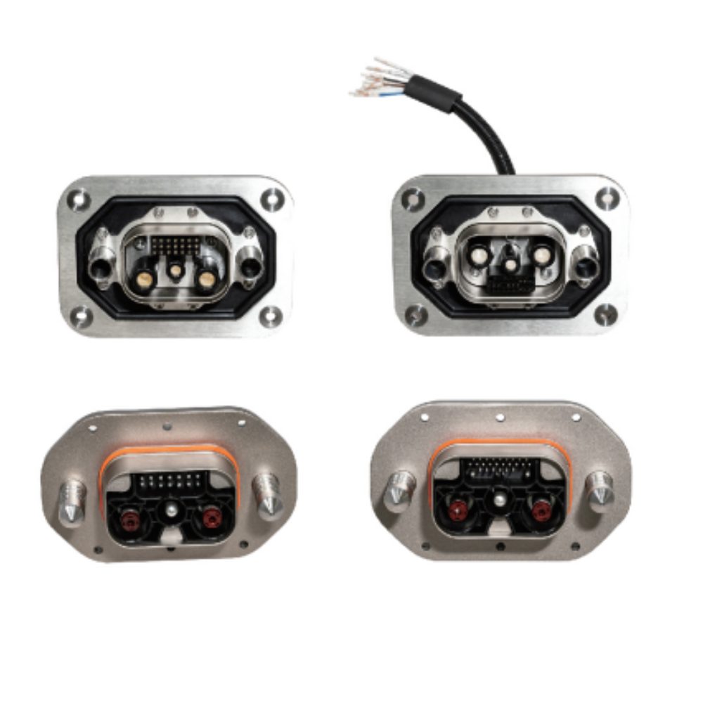
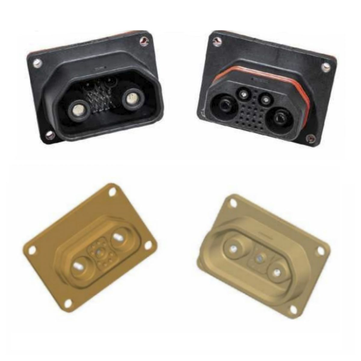
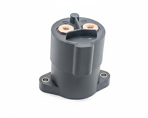
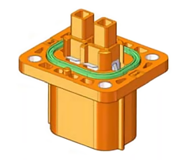
The first is the board end seal:
The board end is the connector socket end using four screws using mechanical connection installation. This is a more common structure, but there is also some more special structure.
Board End Seal
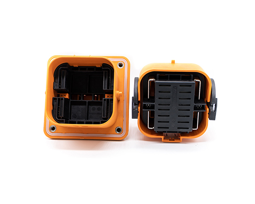
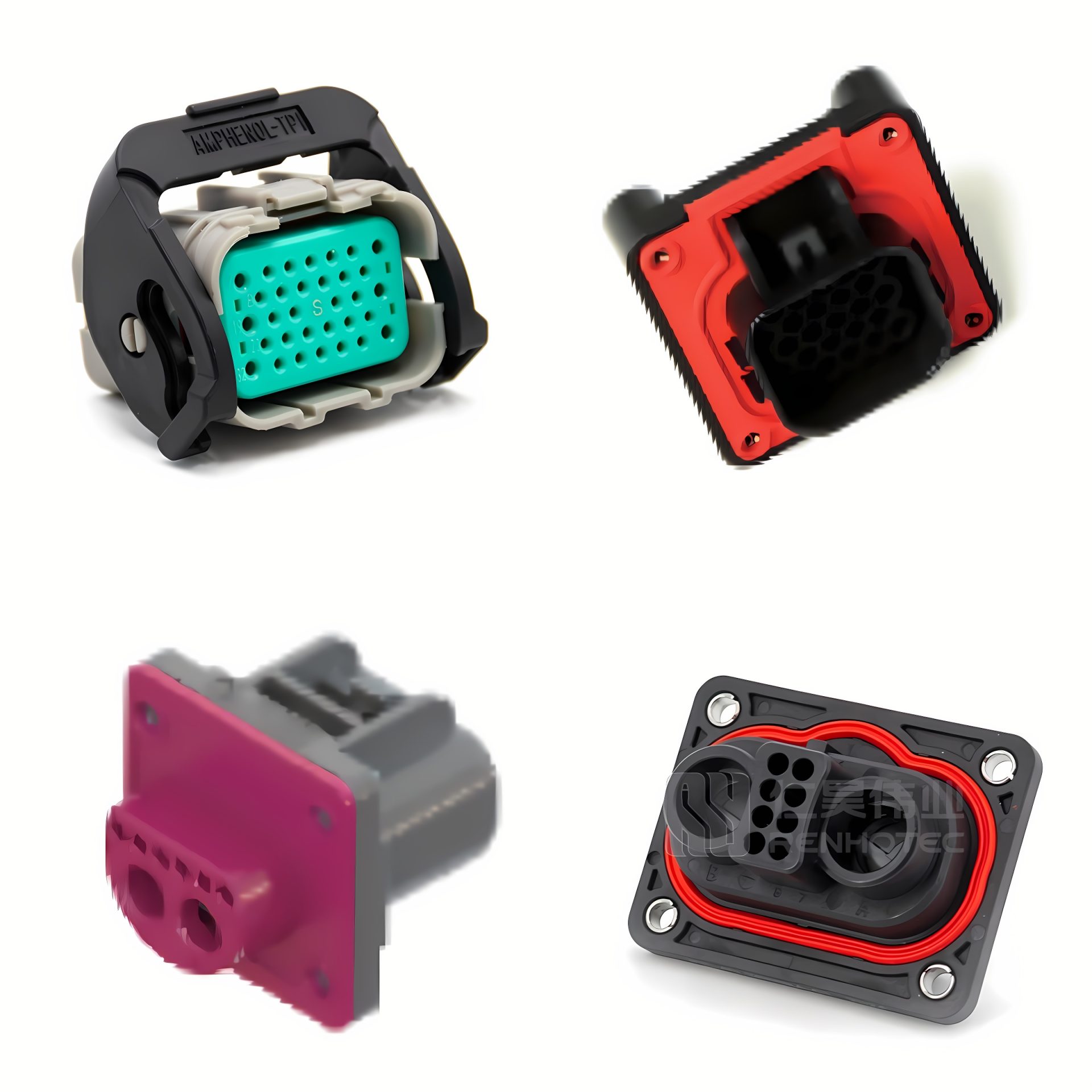
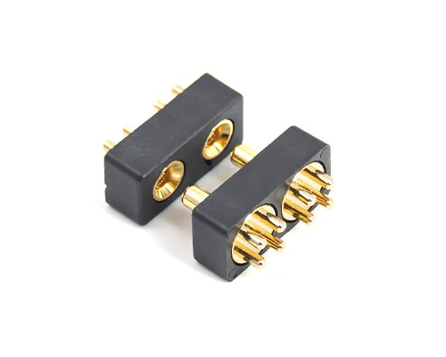
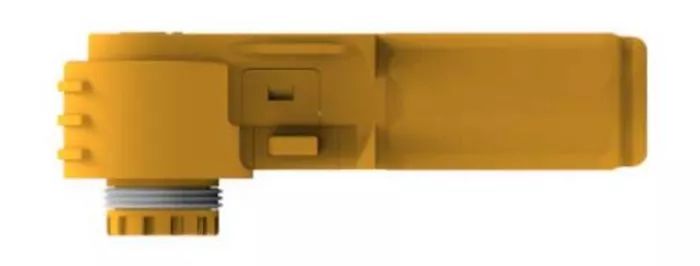
The second is the headstock to plug seal:
The headstock to plug is the male end containing the female end or the female end containing the male end of the middle using rubber parts for radial and axial protection between.
Headstock to Plug Seal
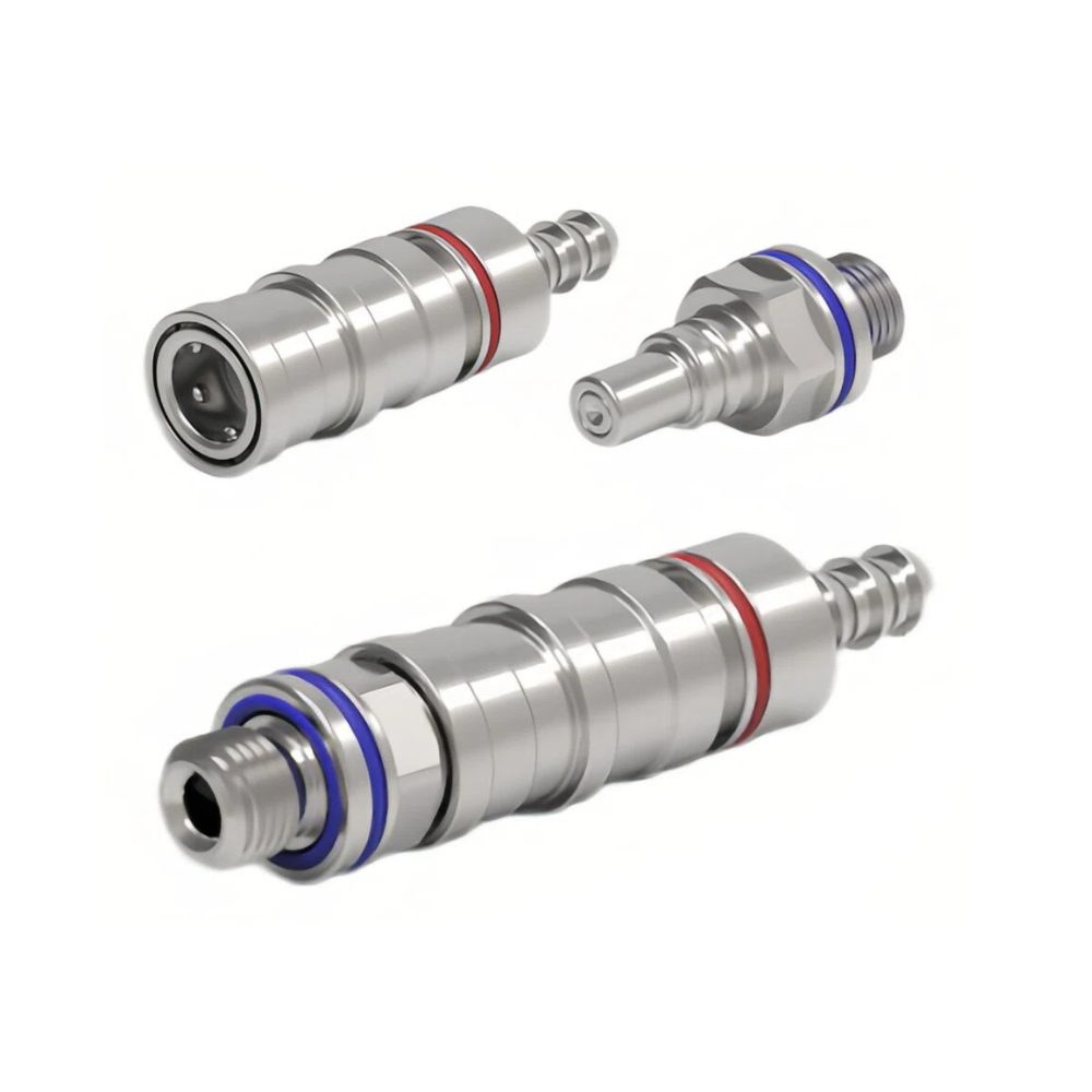
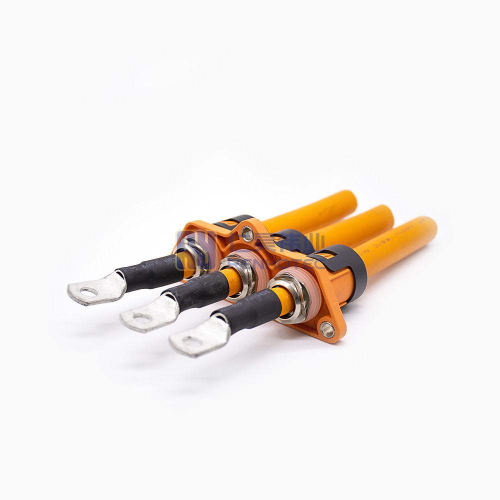
The third is the end-of-line seal:
The protective seal between the end-of-line automotive connector and the cable.
End-of-line Seal
For electric vehicles and high-voltage connector, with the development of the market, the host plant on the performance of product protection requirements is also increasing. The industry’s early development, IP67 protection requirements have been able to meet most customers. But later, as the market appeared in the automotive connector product protection failure, resulting in product leakage, insulation failure, and even ablation cases are increasingly coming.
Protection requirements gradually improve the development trend of electric vehicles, but the current IP67 requirements can not meet the normal use of the requirements. Of course, this is not absolute, but it also depends on the location of automotive connectors in the car layout. According to the high-voltage circuit terms, the whole car arrangement will be suspended in the car chassis underneath. So, most of the high-voltage automotive connectors will be in the chassis near the ground or the hub’s location.
When some bad weather, such as harsh weather, heavy rain, or severe cold weather, your tires bring up water will impact these car connectors. When the car is driving at high speed and wading through water, the instantaneous water pressure rushing to the car connector will be very high. Therefore, IP67 is sometimes difficult to meet the actual use requirements. So IP67 is sometimes difficult to meet the actual requirements of use.
For this point, the domestic QC/T1067 and foreign standards USCAR will be automotive connector sealing into two levels, S1 and S2. S2 level, the occasion applies to the lower chassis position; the recommended is 6K and 9K. If the automotive connector is not arranged in the above location. The IP67 design can meet the requirements of the whole car.
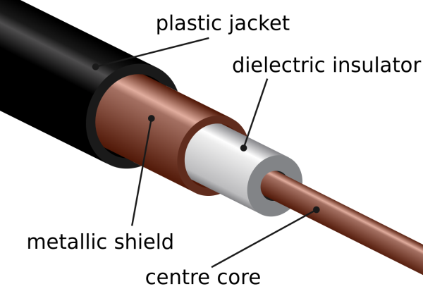
Electric vehicles have a lot of electronic devices; the current will generate magnetic fields, and the whole vehicle components can resist interference. For high-voltage systems, shielding automotive connectors and cables is very important. But we have to prioritize the system-level arrangement, which is a prerequisite.
If your OBC (On board charger), the location of your arrangement, including the DC-DC in the system, is not itself, it may have some inherent problems. Even if the automotive connector does a good job, there will be various signal interference problems. So first consider the system type, followed by the parts level.
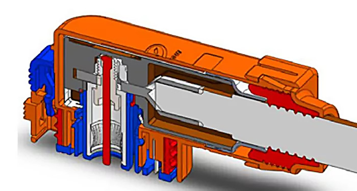
For automotive connector shielding effectiveness, it generally will be used in two ways. The first way we have on some plastic automotive connectors, there will be a metal shield inside. The cable shield will be connected to the shield of the metal shell, forming an effective 360 ° shield. The second way, most of the high-voltage small current connection. There will be no secondary connection, will be used to connect with the cable shield.
This way is also a common way of existing manufacturers, including some of the more well-known domestic OEMs are also considering this way. We call spring contact, in fact, a spring connection. The benefits of this structure are also many because the size and space will be smaller, and it will have more contact points. There are many manufacturers of this structure. The main representative companies like BMW Spring in Switzerland, Basel in the United States, etc. They have a lot of practical and mature application cases in this area.
In most cases, for the connection between the wire and the shield, we will use the form of metal inner and outer rings, crimping, placing the shield between the two metal rings, and making the shield and the metal ring tightly fixed through cold compression deformation. In addition, we also have a shielding method. It replaces the spring connection through a structure similar to a strap spring. This structure often applied to harsh environment connectors products, the technology is mature.
This structure is suitable for the shielding of new energy-electric vehicles and can meet the performance requirements. And at the same time, a punching part is suitable for mass production and cost-effective.
6. Automotive connector material
Automotive connector insulation parts material generally chooses PA66, PBT, ABS, PC, etc. Contact parts material generally choose brass, phosphor bronze, beryllium copper, etc., but now more materials used abroad is copper-nickel-silicon material. Automotive connector shell material is generally divided into plastic and metal two materials.
On how to choose plastic material or metal material, there are generally several reference points as follows.
(1) Lightweight
Due to the demand for lightweight vehicles, passenger car manufacturers will try to meet the premise of product performance and choose plastic automotive connectors to control the vehicle’s weight.
(2) Product use environment
Due to the mechanical strength of metal materials than plastic. So in some of the harsher environments, metal automotive connectors will be more suitable. For example, like special vehicles, dump trucks, as well as the entire vehicle in the arrangement of the electrical connection parts without protection. At this point, metal compared to plastic automotive connectors in the environment and mechanical strength is slightly better.
(3) Shielding to achieve the way
For shielded automotive connectors, as the metal automotive connector shell is used to conduct shielding, the formation of a shielding protection carrier. In general, metal automotive connectors are easier to achieve a more excellent shielding performance than plastic automotive connectors, a more compact form factor.
One thought on “Analysis of High Voltage Connector Technology and Design”
Marc Vandeputte says:
For EV, the screen currents in the DC link (battery to invertor) are much lower than the screen currents in the AC link (3 phases from invertor to motor). These high AC screen currents are caused by induction and are related to the cable length and applied frequencies (motor pole size and requested RPM) for a given high core current. Connectors and screened cables that can handle these high screen currents are seldom.


For EV, the screen currents in the DC link (battery to invertor) are much lower than the screen currents in the AC link (3 phases from invertor to motor). These high AC screen currents are caused by induction and are related to the cable length and applied frequencies (motor pole size and requested RPM) for a given high core current. Connectors and screened cables that can handle these high screen currents are seldom.