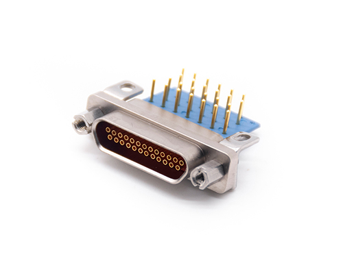
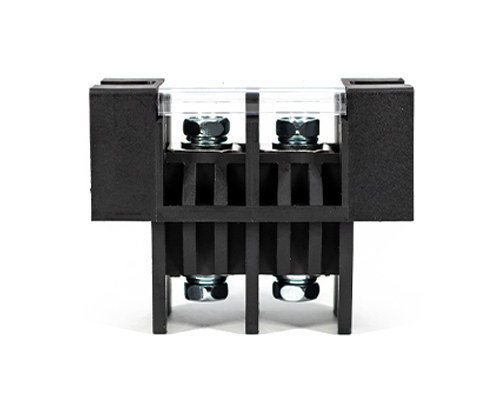
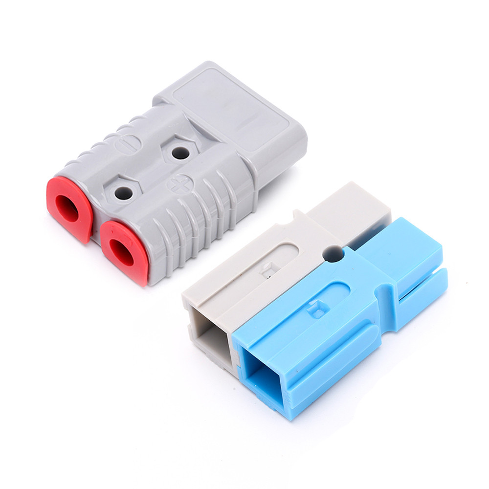
The Rectangular Connector is widely used in aerospace, medical instruments, consumer electronics (such as computers, TVs, game consoles, etc.), industrial control equipment, communication equipment, and automotive electronics. With its reliable connection performance, diverse specifications, and relatively convenient plug-in and unplug operations, it has become an indispensable component in various electronic and electrical applications.
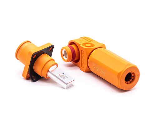
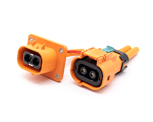
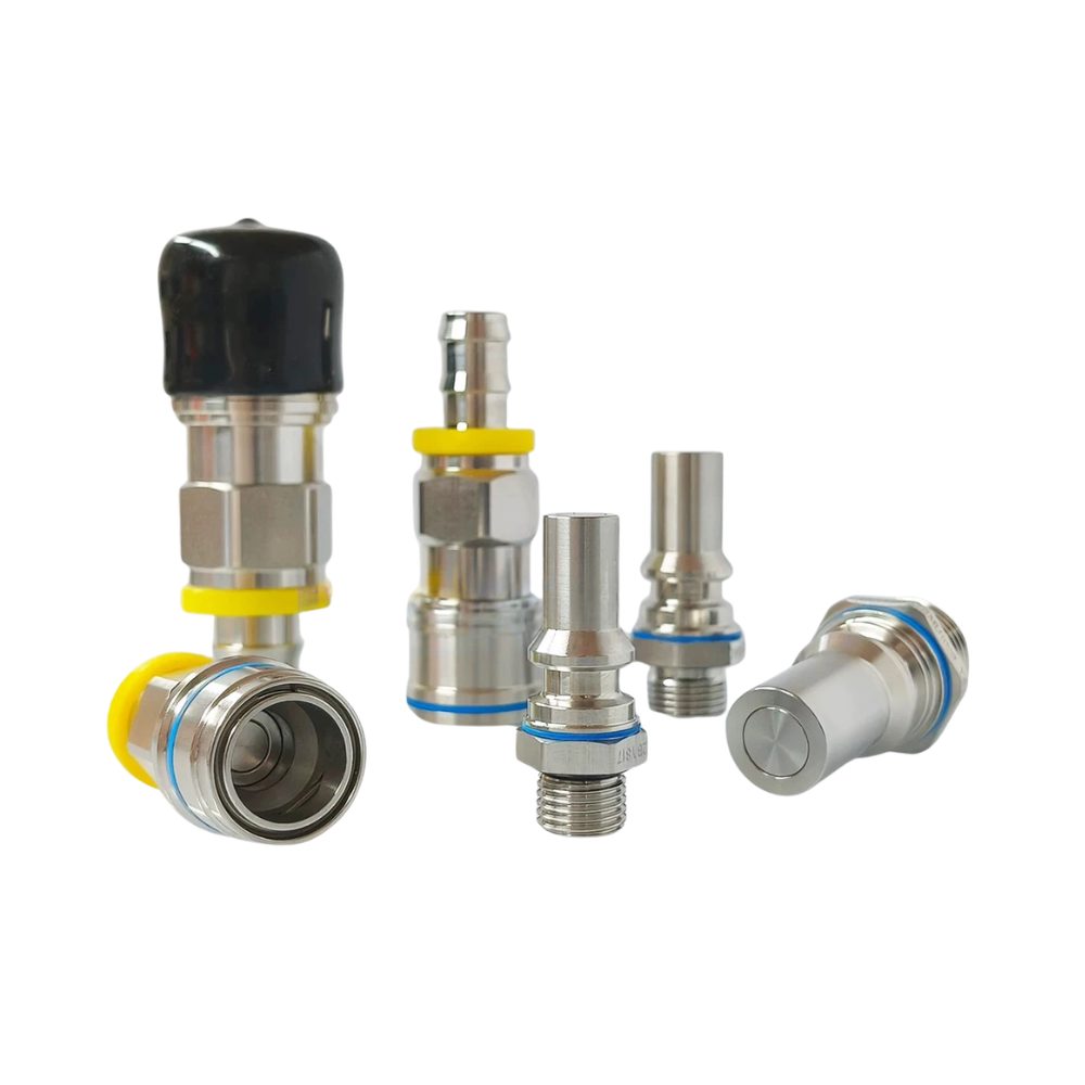
High Voltage Connectors are widely used in EV power systems, renewable energy installations, and industrial high-voltage circuits. Renhotec’s series drives the building of efficient, safe, and sustainable electrical ecosystems, meeting current technological demands.
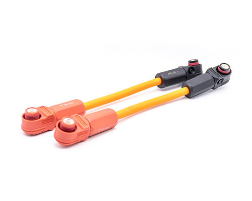
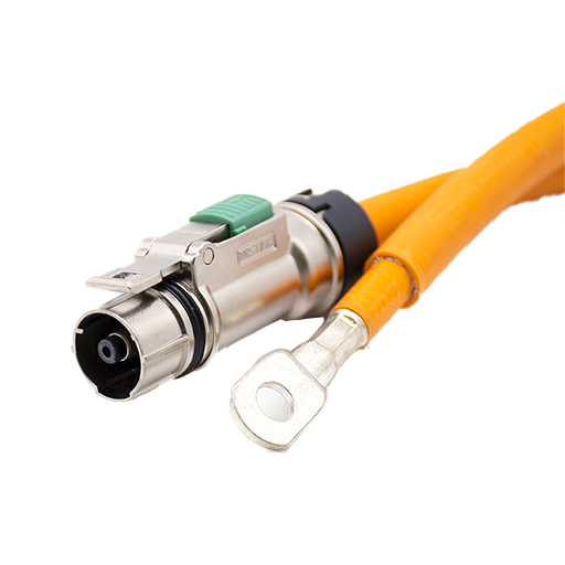
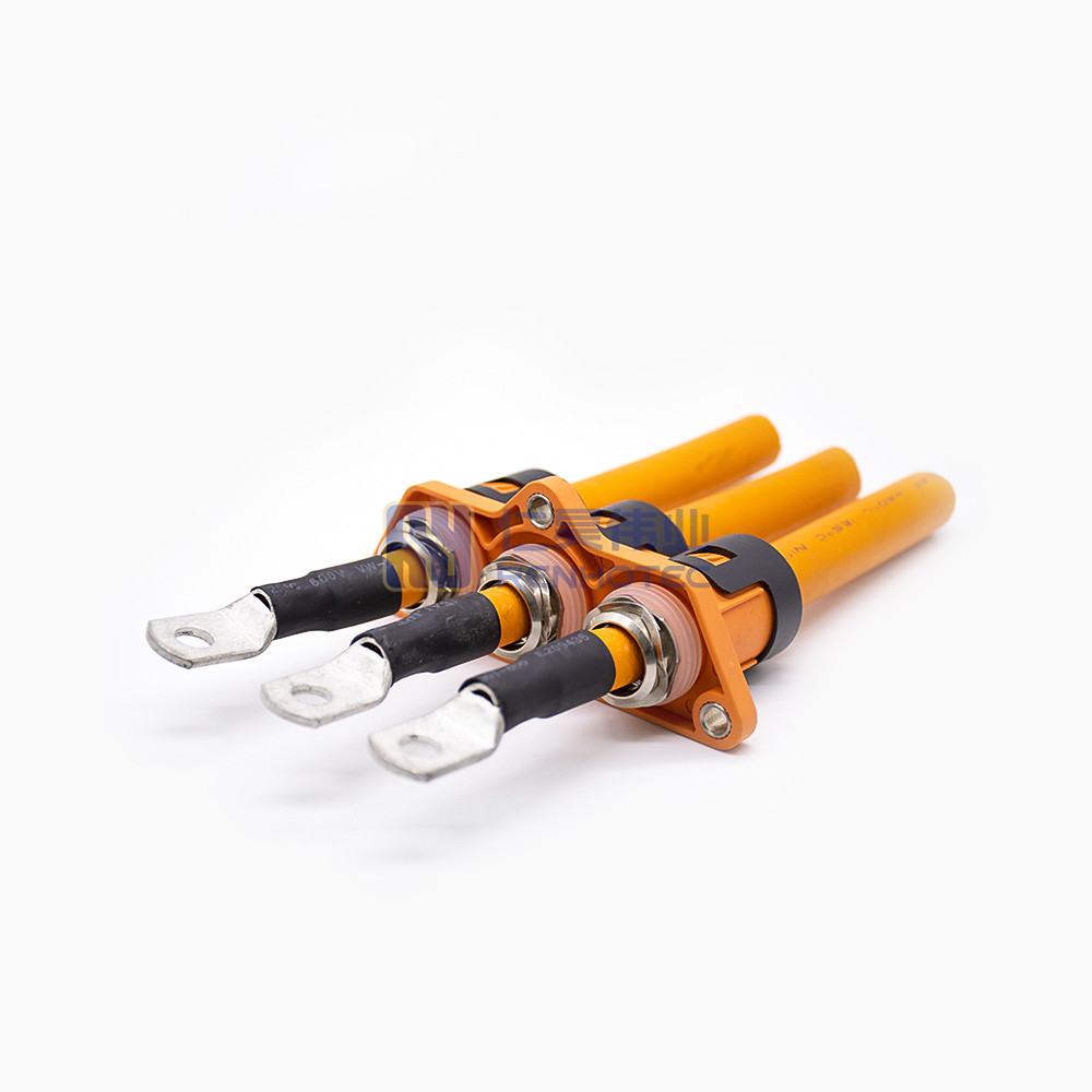
Renhotec EV Cable, crafted with top-notch conductive materials and meticulously engineered insulation, showcases outstanding impedance control and voltage-withstanding properties. Its design combines flexibility and durability to meet a wide array of installation needs. This cable is widely utilized in grid interconnections, large-scale industrial power supply systems, and high-voltage renewable energy projects, enabling smooth and efficient power transmission.
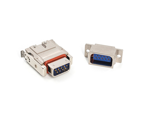
Renhotec, as a professional supplier, offers a comprehensive range of these Signal Transmission Connector products. Whether it is the high-reliability applications of the metal series or the wide adaptability of the plastic series in consumer electronic products, Renhotec can provide customers with high-quality options to meet the diverse requirements of signal transmission connections in different industries and scenarios.
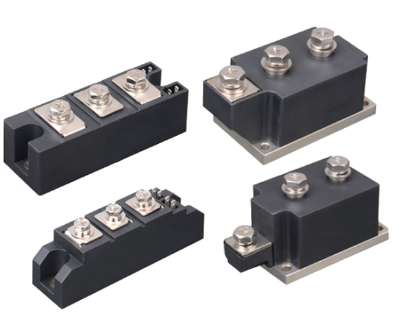
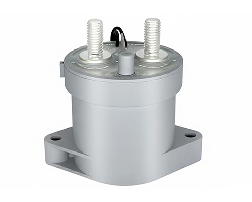
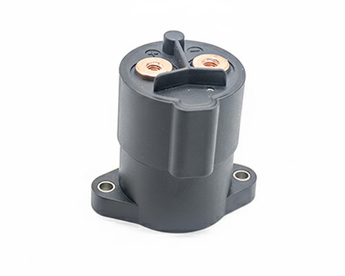
Renhotec, active in electrical components, offers High Voltage DC Contactors in Epoxy Resin Sealing and Ceramic Sealing variants, with a 20A – 1000A current range. The Epoxy Resin Sealing one is cost-effective and protective. The Ceramic Sealing variant excels in thermal stability and insulation. They’re widely used in EV charging, renewable energy grid, and industrial high-voltage DC power distribution for reliable circuit control and current interruption, providing comprehensive solutions for multiple sectors.
Electric Vehicle High-Voltage Connectors Ultimate Guide
HV connectors are an essential component of electric vehicles. This article discusses the development history, technical features, and product testing of high-voltage connections.
The development of HV connectors goes hand in hand with the development of electric vehicles.
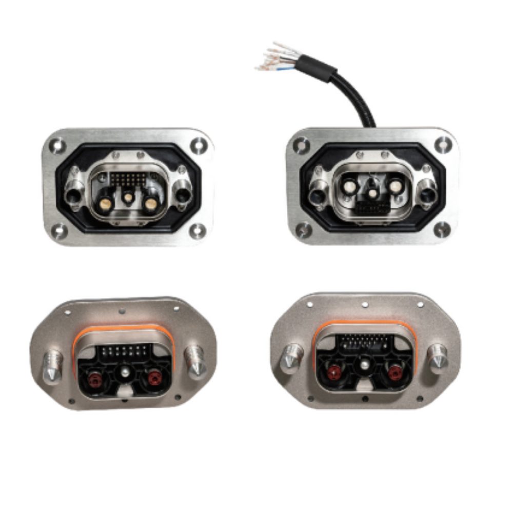
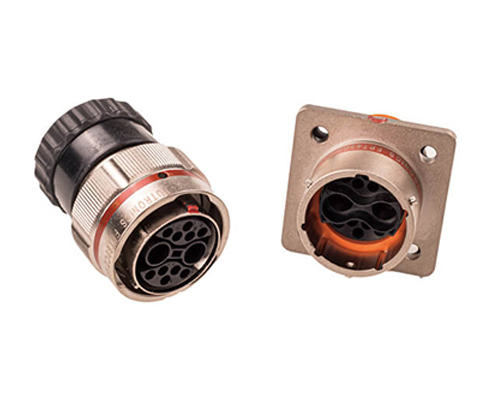
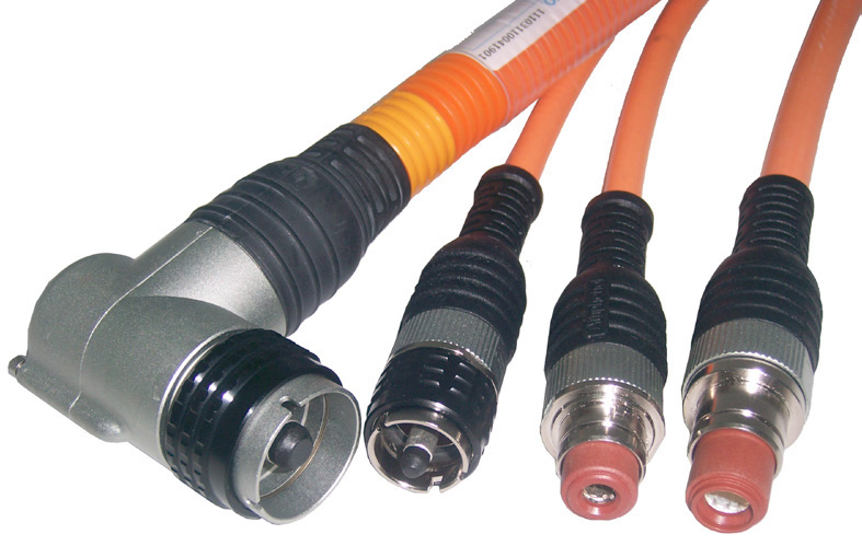
1. The 1st generation of high-voltage connectors mainly evolved from industrial connectors.
The housing of this generation is metal. It does not have a HVIL function.
The 1st generation of high-voltage connectors, a more representative product, is the Amphenol HV series of metal connectors.
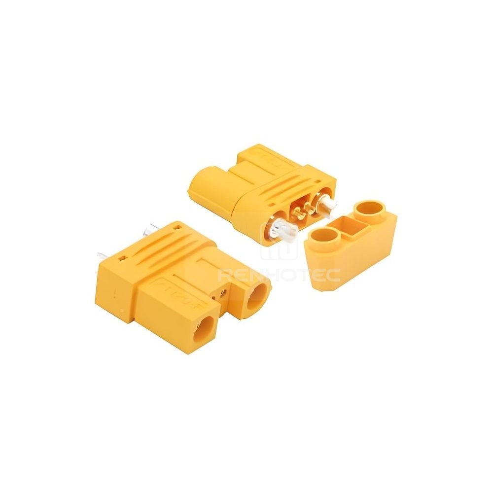
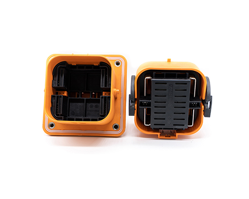
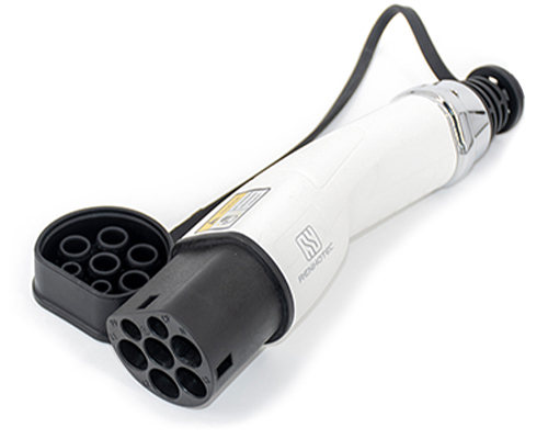
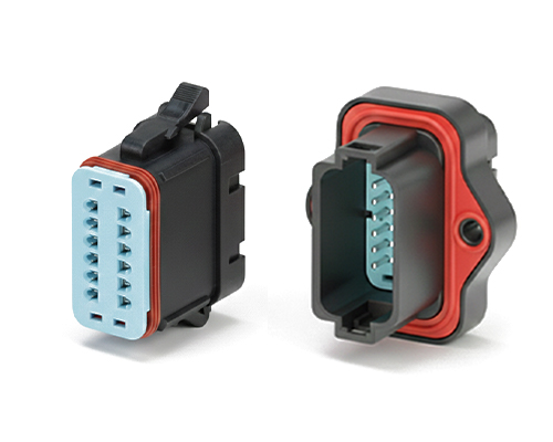
2. The 2nd generation of HV connectors added a HVIL function based on the 1st generation.
And the connector housing has also been changed from metal to plastic.
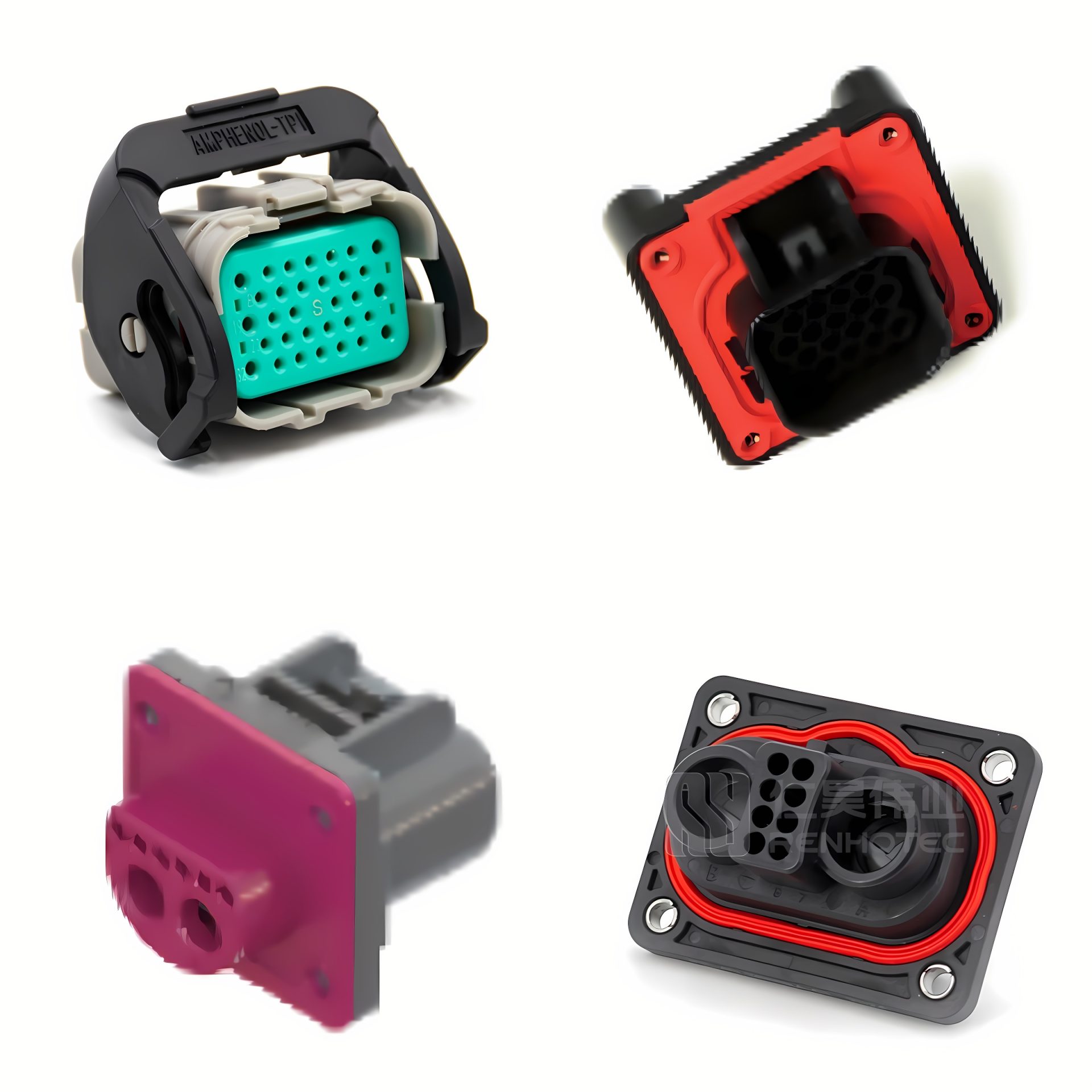
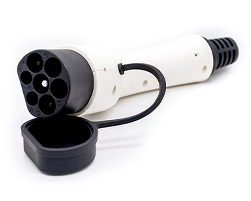
3. The 3rd generation HV connectors have shielding and HVIL functions.
Among them, the 800 series products are more famous.
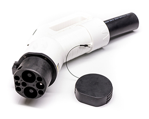
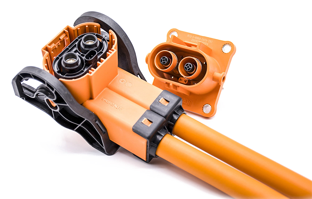
4.The 4th generation HV connectors have the functions of shielding, HVIL, and secondary unlocking.
Among them, the 280 series products are more famous. These products achieve secondary unlocking function through the mechanical structure, more secure.
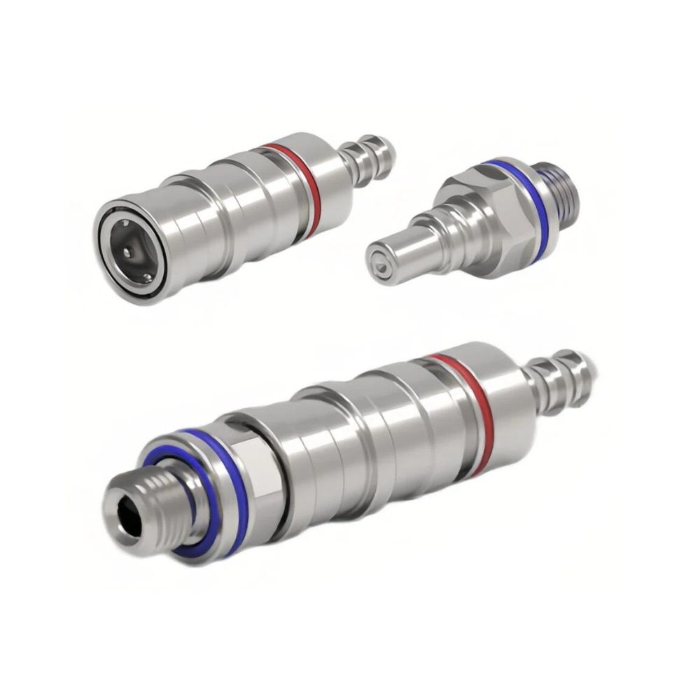
5. Future generations of high-voltage connectors may add cooling capabilities.
For example, we can use liquid or air cooling to increase the density of energy transferred during high-power charging.
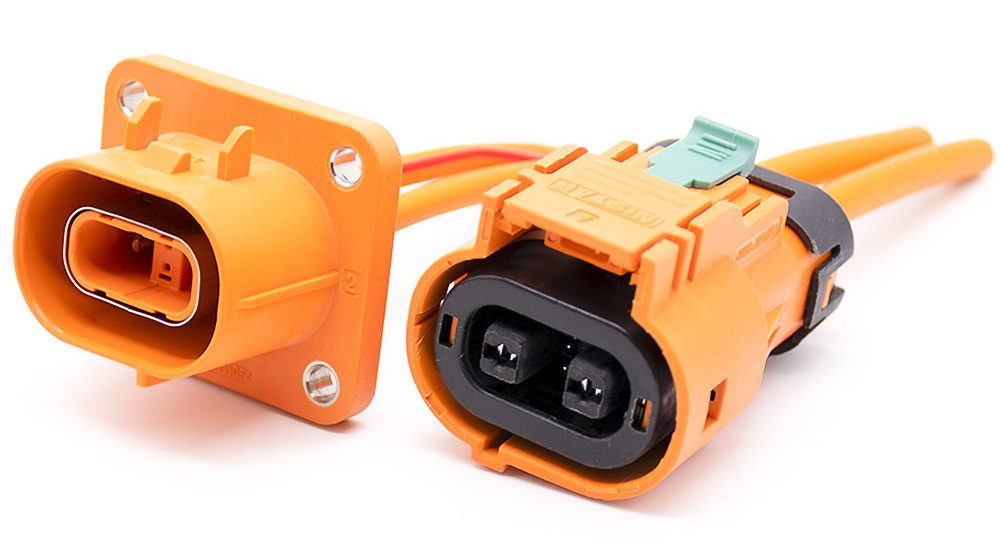
Technical characteristics of HV connectors for electric vehicles
In the electric systems of new energy vehicles, the HV connection system has a pivotal position. It is like a vascular system that organically integrates all the crucial organs in the human body.
The battery’s main positive and negative circuits are similar to the human aorta and main vein. Other circuits are similar to human arteries, veins, and capillaries.
The HV connection system is an important guarantee to ensure that electric vehicles’ energy transfer is safe and reliable.
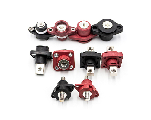
1. HV Connector Classification
At present, HV connectors can be classified in two ways according to terminal type and structure.
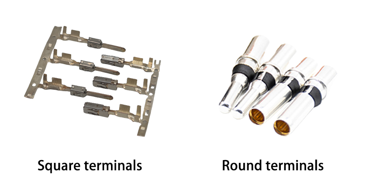
According to the Terminal Type
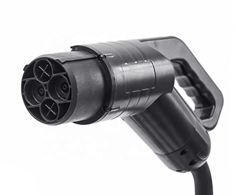
1) Square Terminal Structure.
This kind of terminal uses the terminal technology of stamping. It has a lower production cost but a higher die sinking cost. More widely used in the slight current below 40A.
Some Japanese and American car companies with high-current connectors use square terminal structures, such as Tesla and Toyota.
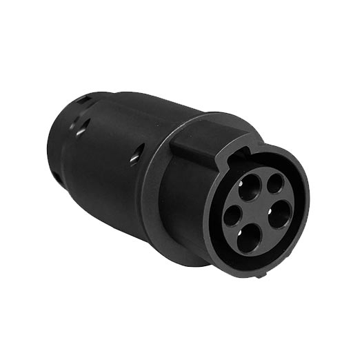
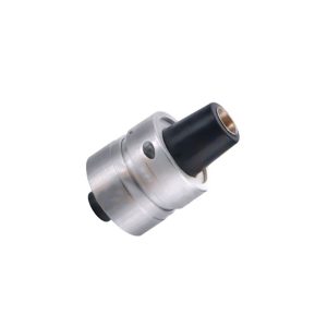
2) Round Terminal Structure.
This type of terminal uses machined terminal technology. It has a higher production cost, but a lower die sinking cost. The more representative products are the TE HVA800 series.
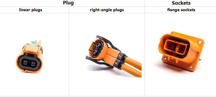
According to the Type of Structure
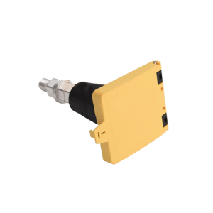
According to the installation method, the connectors can be divided into plugs and sockets. Plugs are available as linear plugs and right-angle plugs.
Sockets are available as flange sockets, right angle sockets, and linear sockets.
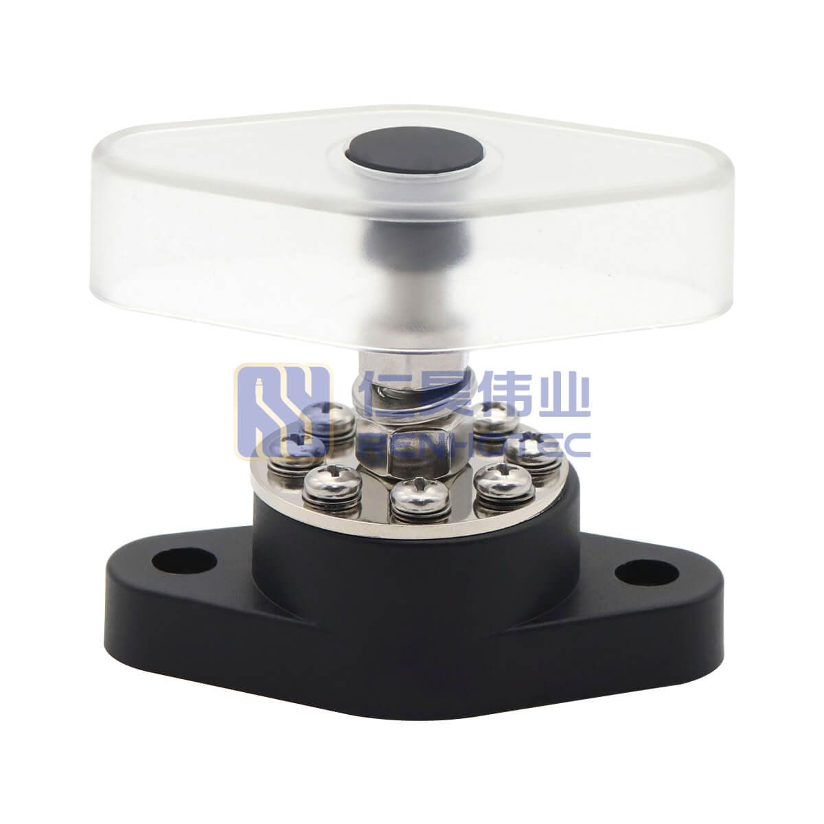
2. High Voltage Interlock
High Voltage Interlocking (HVIL) is a safety design method for managing high voltage circuits with low voltage signals circuits. HVIL is commonly used in high-voltage electrical circuits, such as HV connectors, MSD, high-voltage distribution boxes, and other circuits.
When unlocked under live conditions, connectors with HVIL can be disconnected through the logic timing of HVIL.
The disconnection time is related to the contact length difference between the HVIL terminal and the signal terminal. Typically, the system response time to the interlock terminal circuit is between 10 and 100ms.
There is a safety risk of powered plugging and unplugging when the connection system separation time is less than the system response time.
Secondary unlocking solves the disconnection time problem very well. Usually, secondary unlocking can effectively control disconnection time to more than 1s to ensure safe operation.
3. Secondary Unlocking
There are two ways of secondary unlocking.
1) One is achieved opposite from the typical pull-out, such as the mainstream HVA800 HVC800 series HV connectors.
The booster plate hand and connector separation direction is opposite when the connector is pulled out, increasing the response time when pulling out and achieving the secondary unlocking function.
2) The other one is the mechanical secondary unlocking function.
When pulling out the connector, the first time can only pull out to the position where the HVIL terminal is disconnected. Then a secondary operation is required to separate the signal terminals, thus enabling the secondary unlocking function.
Compared with the first method, mechanical secondary unlocking has higher security, but its structure is also more complicated.
4. Locking Structure
Connector Position Assurance (CPA) is a snap structure used to increase the strength of the connector locking device.
CPA can effectively protect the connector plug and socket connection to prevent accidental loosening or poor contact during the car’s operation.
The working principle of CPA. When the main locking structure is locked, the CPA assists in locking. At this time, the main locking structure is not easily loosened by the external environment.
The CPA needs to be unlocked before the main locking can be unlocked.
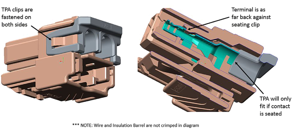
5. Terminal Position Assurance
Terminal Position Assurance (TPA) is used for secondary protection and limiting terminals. TPS prevents the terminals from dislodging under external tension.
Usually, we use it in harsher environments.
This composition will generally contain two kinds of holding structures. One is the terminal holding structure, and the other is the TPA holding structure.
6. Terminal Crimping Evaluation
Terminal crimping is the core process of the connector industry. Evaluation of terminal crimping consists of the following points.
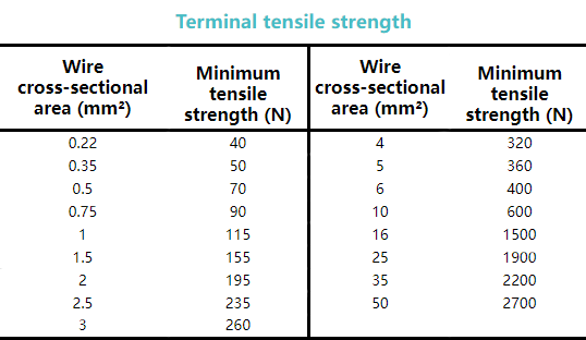
1) Terminal Tensile Strength
The minimum tensile strength of the crimp between the terminal and the wire. The following table shows the main parameters.
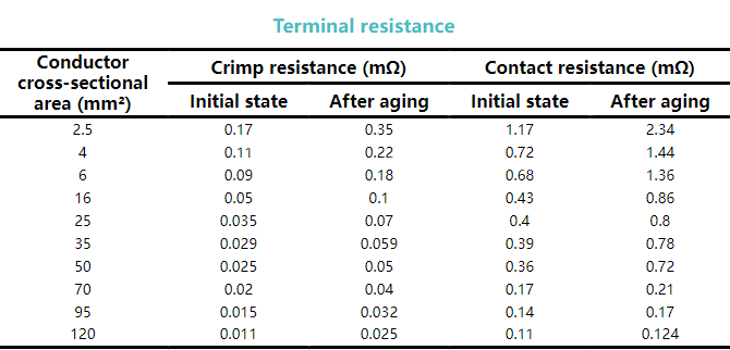
2) Terminal Resistance
Resistance test at the crimp. The following table shows the terminal resistance.
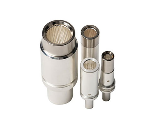
3) Terminal Crimp Profile Analysis
Truncate, grind and polish the effective crimp area of the terminals after crimping. Then use professional equipment for compression ratio testing.
It is required that when put about 5~10 times, there is no visible gap between the compressed cables, and the compression ratio is controlled at 80%~90%.
4) Terminal Temperature Rise
The general requirement is that the temperature rise of the terminal does not exceed 55K.
5) Terminal Crimp Height and Width
Determine the crimp height and width of the terminals that pass the previous test, and control CPK during the process.
7. Comprehensive testing of HV connectors
We need to conduct comprehensive testing of product performance during the production of HV connectors and wiring harnesses. Such comprehensive testing plays a vital role as a gatekeeper.
Generally will contain the following items.
1) Withstand Voltage Test
To detect the risk of poor voltage withstand during the assembly of the product. Usually, this type of test requires 100% testing.
2) Insulation Test
Mainly for the product in the assembly process whether there is a risk of poor insulation.
3) Circuit Conductivity
To Detects whether each circuit corresponds to each other after the connector is assembled.
4) Airtight Test
Apply 47.8kPa air pressure to test the sealing of the connector. We can adjust the test time, leakage value and other parameters according to the product characteristics. Applicable to the finished connector or harness assembly testing.
5) Shielding Circuit Test
To detect the resistance value in the shielding circuit. In general, the shielding resistance should be less than 10mΩ.
Test system construction
Since the performance of the HV connectors adirectly related to the safety of the whole new energy vehicle, the product requirements are incredibly high.
In addition to getting the standard compliance report, there will be DV and PV tests in the factory design and production stages.
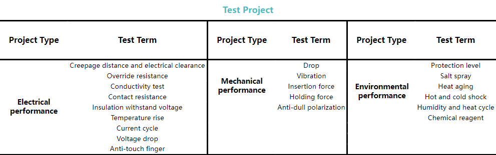
The test mainly contains the following aspects.
1)Electrical Performance
Electrical performance test includes tests of electrical parameters as well as electrical safety. Such as current cycle, lap resistance, insulation withstand voltage test, etc.
2)Mechanical Performance
The mechanical performance test contains tests of pull-out force, vibration resistance, and mechanical structure. Ensure the convenience and reliability of the installation, connection, and maintenance of the product.
3)Environmental Performance
Including salt spray resistance, thermal aging, temperature shock, damp heat cycle, etc. Test methods and requirements will vary according to the product’s use environment.
Conclusion
A high-voltage connection system is an integral part of new energy vehicles. Its reliability problems will directly affect the safety of electric vehicles.
This article introduces the development history, technical characteristics, and testing requirements of HV connectors for electric vehicles.
Please leave your message in the comment section if you have any questions.
One thought on “Electric Vehicle High-Voltage Connectors Ultimate Guide”
Kamesh says:
Hi M/s, Renhotec,
This is kamesh from the HTL from Chennai. We required below connector 2D &3D drawings & samples also. Pls share the specification details.
HGL61-HVC011-002PX
HGL61-HVC011-002PY
LSC01-5M32SX-01


Hi M/s, Renhotec,
This is kamesh from the HTL from Chennai. We required below connector 2D &3D drawings & samples also. Pls share the specification details.
HGL61-HVC011-002PX
HGL61-HVC011-002PY
LSC01-5M32SX-01
Awaiting for your valuable reply.
With Best Regards,
S.Kamesh
.