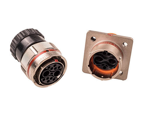
The Rectangular Connector is widely used in aerospace, medical instruments, consumer electronics (such as computers, TVs, game consoles, etc.), industrial control equipment, communication equipment, and automotive electronics. With its reliable connection performance, diverse specifications, and relatively convenient plug-in and unplug operations, it has become an indispensable component in various electronic and electrical applications.
High Voltage Connectors are widely used in EV power systems, renewable energy installations, and industrial high-voltage circuits. Renhotec’s series drives the building of efficient, safe, and sustainable electrical ecosystems, meeting current technological demands.
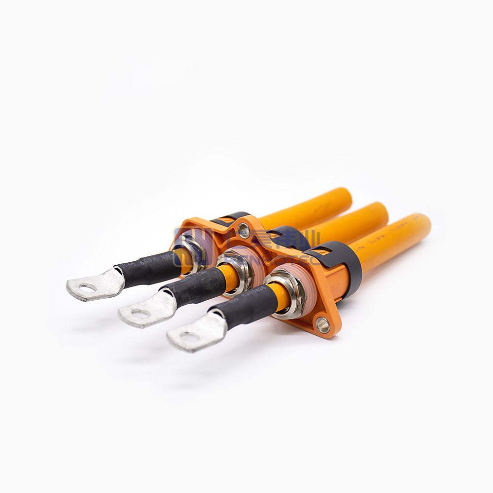
Renhotec EV Cable, crafted with top-notch conductive materials and meticulously engineered insulation, showcases outstanding impedance control and voltage-withstanding properties. Its design combines flexibility and durability to meet a wide array of installation needs. This cable is widely utilized in grid interconnections, large-scale industrial power supply systems, and high-voltage renewable energy projects, enabling smooth and efficient power transmission.
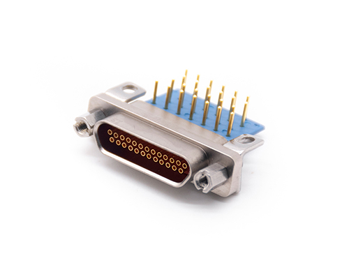
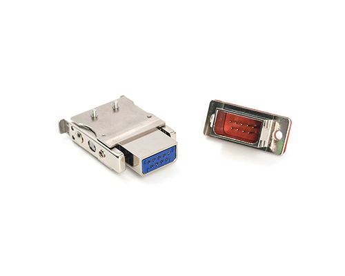
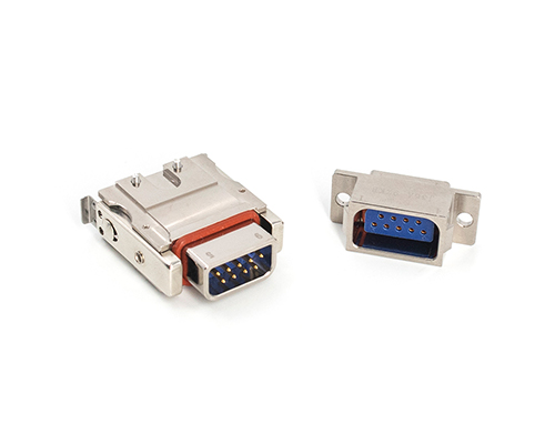
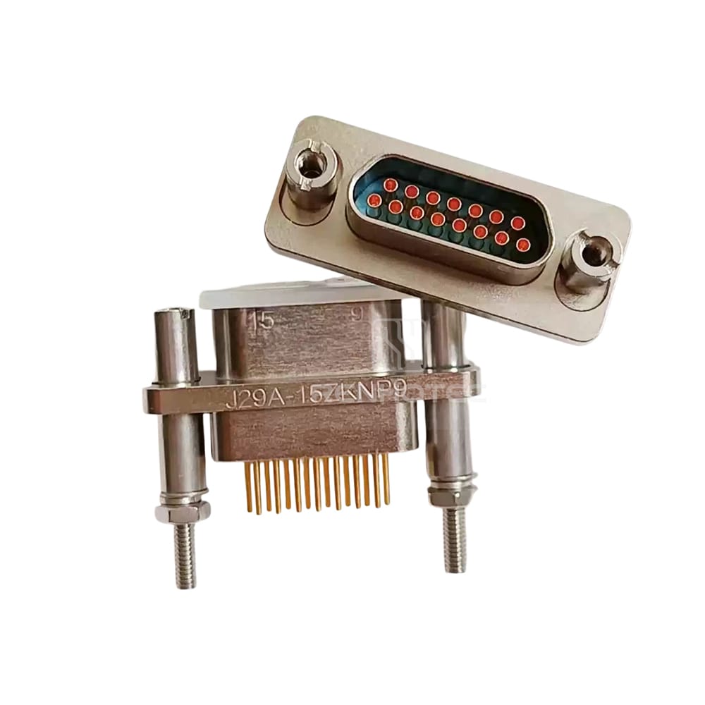
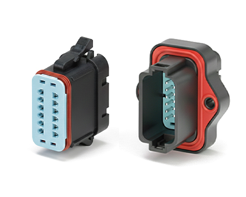
Renhotec, as a professional supplier, offers a comprehensive range of these Signal Transmission Connector products. Whether it is the high-reliability applications of the metal series or the wide adaptability of the plastic series in consumer electronic products, Renhotec can provide customers with high-quality options to meet the diverse requirements of signal transmission connections in different industries and scenarios.
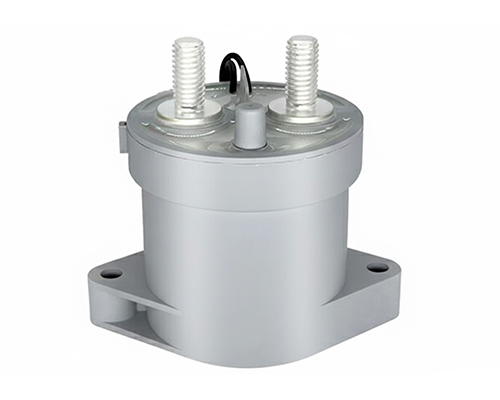
Renhotec, active in electrical components, offers High Voltage DC Contactors in Epoxy Resin Sealing and Ceramic Sealing variants, with a 20A – 1000A current range. The Epoxy Resin Sealing one is cost-effective and protective. The Ceramic Sealing variant excels in thermal stability and insulation. They’re widely used in EV charging, renewable energy grid, and industrial high-voltage DC power distribution for reliable circuit control and current interruption, providing comprehensive solutions for multiple sectors.
Electric vehicles (EVs) are revolutionizing transportation, with rising sales as people swap traditional cars for greener options. Beyond their eco-friendly appeal, automotives rely on innovative technologies like HVIL (High Voltage Interlock Loop) to ensure safety and performance. This article explores what HVIL is, why it matters, and how it works in practice.
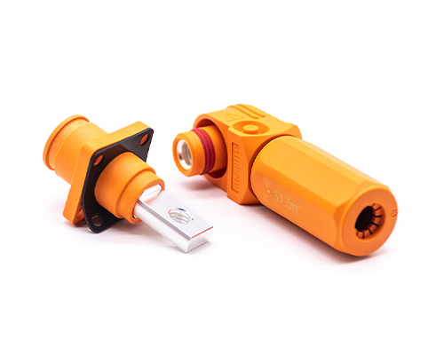
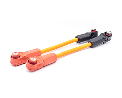
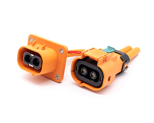
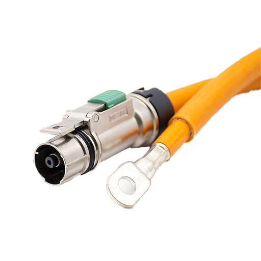
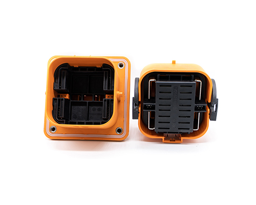
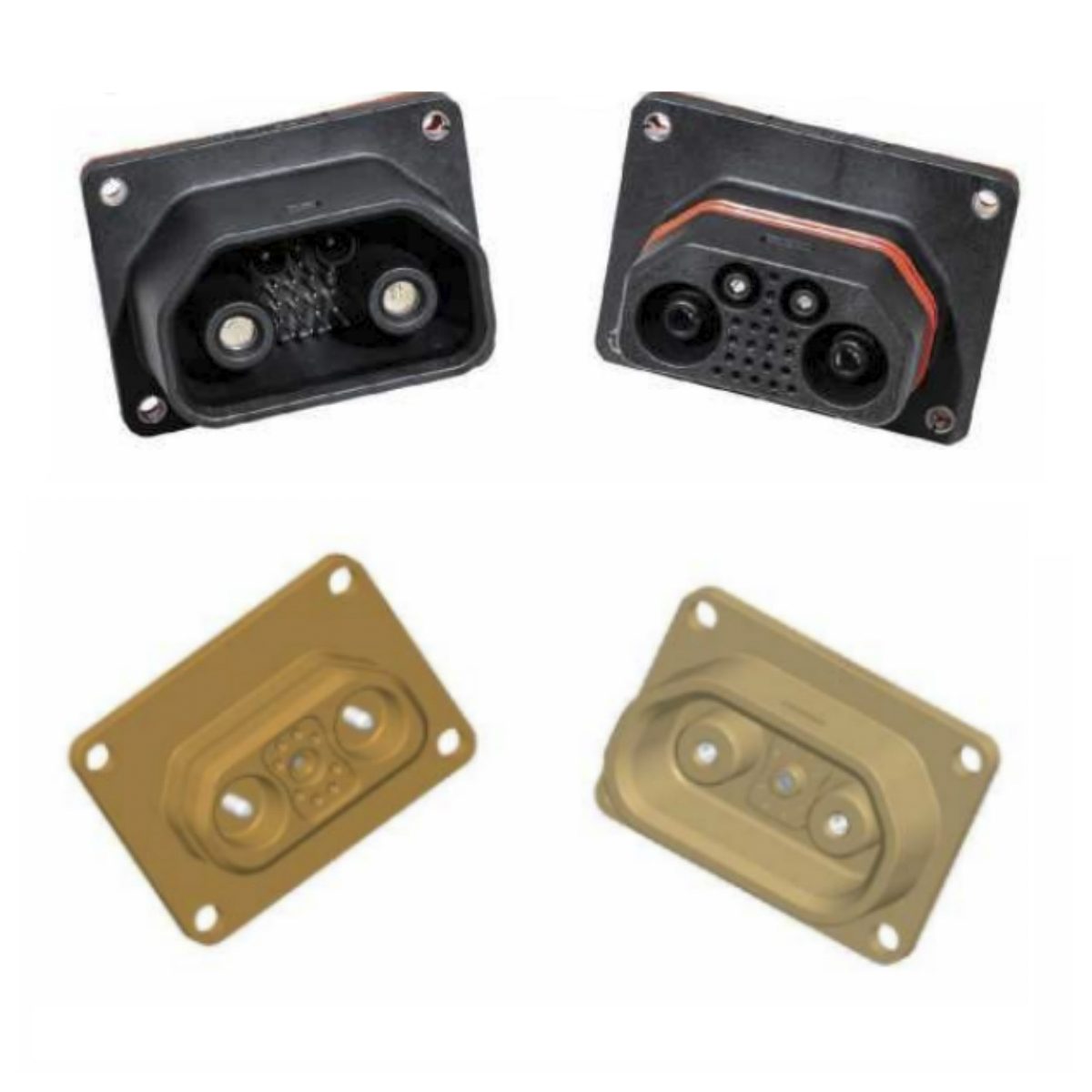
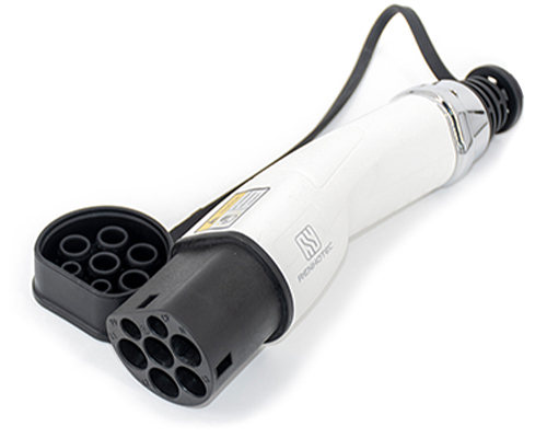
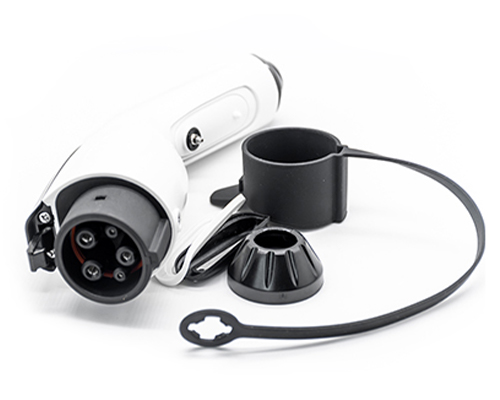
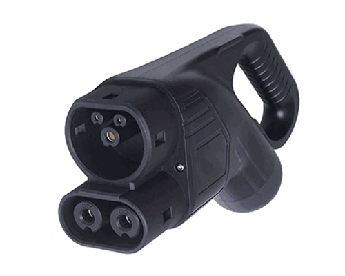
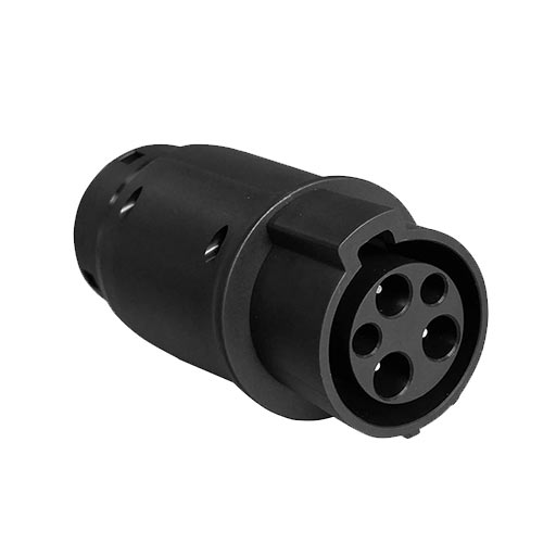
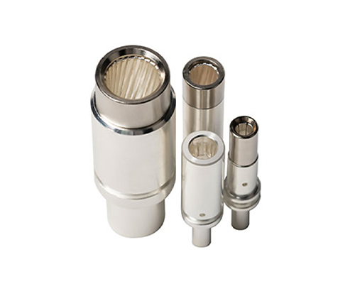
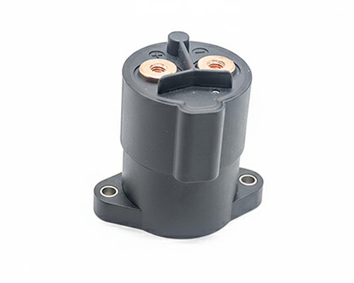
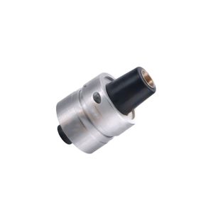
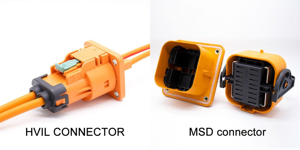
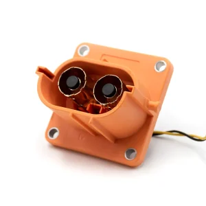
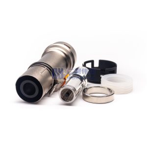
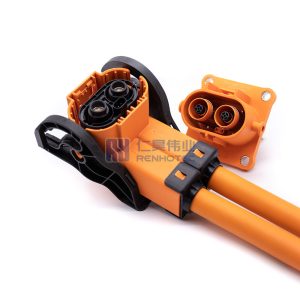
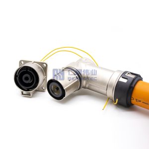
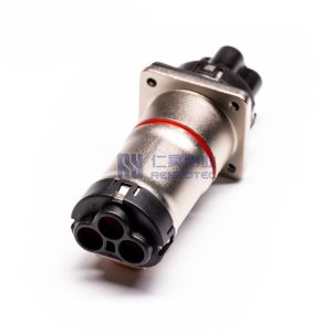
HVIL (High Voltage Interlock Loop) is a safety feature that uses a low-voltage loop to monitor the integrity of a high-voltage circuit.The HVIL system is designed to protect people who may come into contact with high-voltage components of electric vehicles.The main electrical components used in the electric vehicle high-voltage interlock loop are the HVIL connector and the Manual Service Disconnect (MSD connector).
HVIL Connector & MSD Connector
2. Why do Electric Vehicles Need HVIL?
From the perspective of system safety, the potential risks of electric vehicles need to be monitored with the help of technology to reduce risks.
On the one hand, if the high-voltage connection of an electric vehicle is loose, disconnected or damaged during operation, the power will suddenly be cut off, the vehicle will lose power, and it is very easy to cause an accident. At this time, HVIL in EV is like a circuit breaker, which can not only cut off the high-voltage circuit in time to prevent the fault from worsening but also quickly alarm the driver to buy time for emergency response.
On the other hand, when the high-voltage system is running, it is very dangerous to manually disconnect the high-voltage connection point. The high transient voltage generated at the moment of disconnection may break through the air and endanger surrounding personnel and equipment. The HVIL system can effectively monitor and prevent such misoperation.
3. How does HVIL Work?
There are two aspects of high voltage interlock loop design to consider.
How the low voltage circuit can fully detect the connection status of each connection point in the entire high voltage circuit.
How to make the low-voltage circuit complete information transfer before the high-voltage circuit is disconnected.
Let’s start with these two aspects.
High-voltage interlock circuit design principle
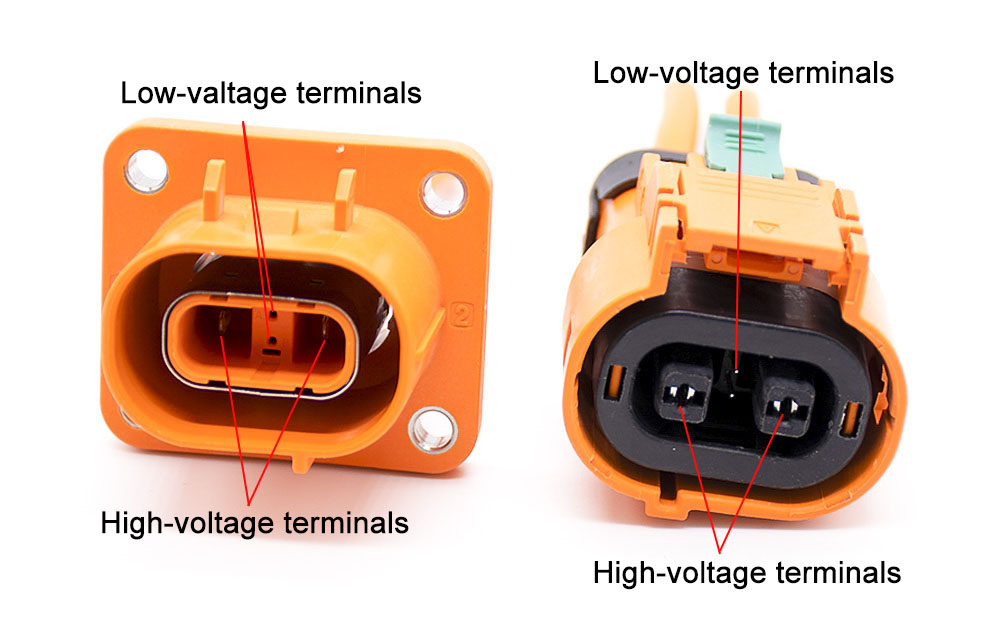
All high voltage connector docking terminals are equipped with low voltage signal terminals.
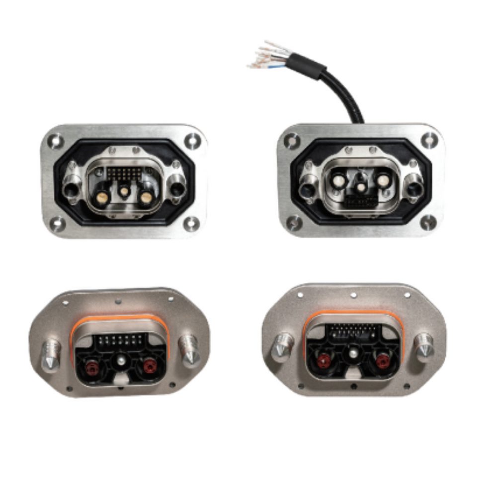
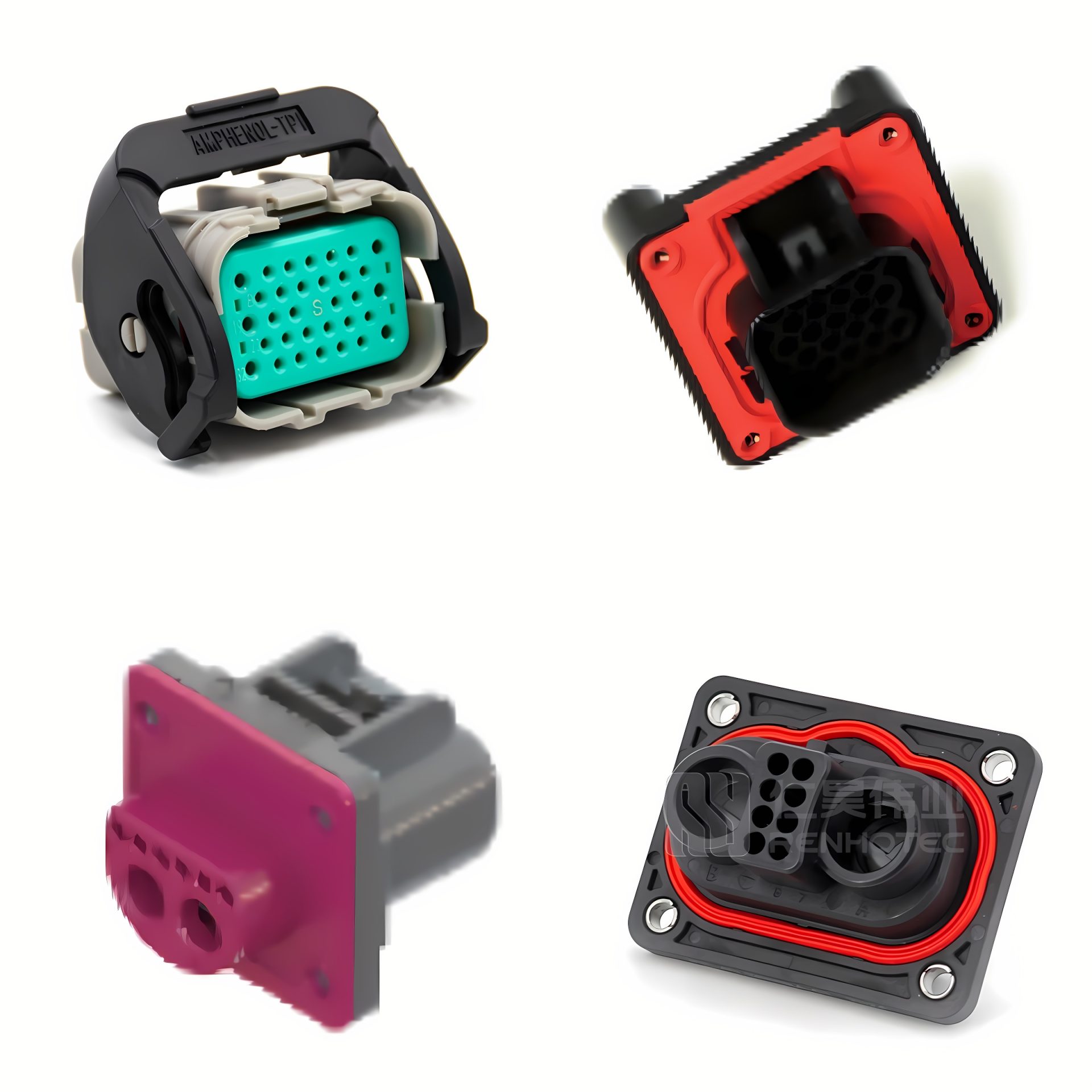
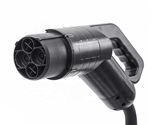
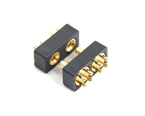
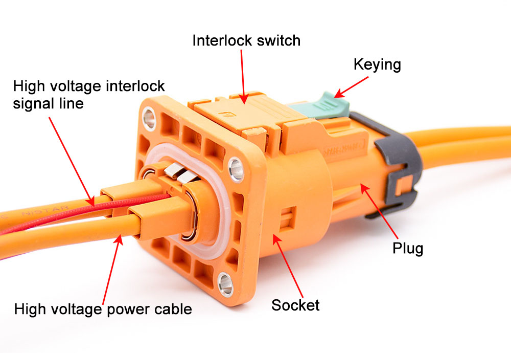
Contact Structure of a HVIL Connector
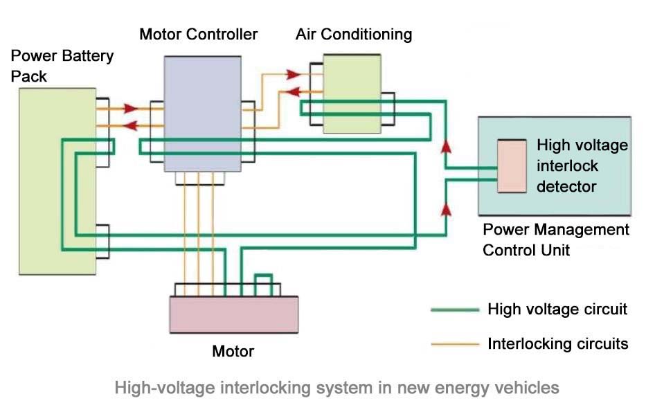
In a HVIL system, the low-voltage signal circuit and the high-voltage circuit are independent of each other. For example, on high voltage, Electrical A and Electrical B together form a complete circuit. We can set up a separate low-voltage signal circuit for each of Electric A and Electric B. We can also connect the low-voltage signal circuits of Electric A and Electric B in series.
As shown below. The high voltage circuit uses the power pack as the power source. There is a low-voltage power supply in the low-voltage circuit, allowing the signal to pass along the low-voltage circuit. Once the low voltage signal is interrupted, it means that one of the high-voltage connectors is loose or disconnected.
Components of the high-voltage interlock circuit
The implementation of high voltage interlocking technology requires the following devices to work together:
HVIL connectors and high/low voltage conductors
Closed low voltage signal circuit
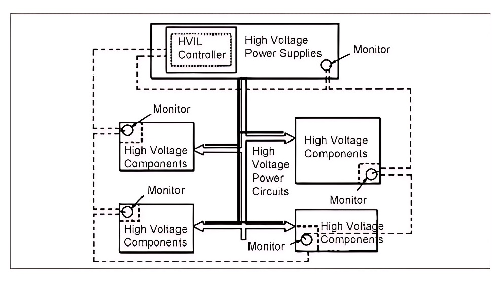
High voltage interlock monitoring circuits and monitors (The monitoring module can be on the BMS or the VCU, or both have monitoring functions separately)
High-voltage relay directly controlled by the high-voltage interlock monitoring signal
High-voltage relay controlled by the VCU according to the high-voltage interlock monitoring results
Hvil Circuit Diagram
There are two types of high-voltage interlock monitors:
One is to monitor whether the high-voltage circuit connection is complete.
The other is to monitor whether the high voltage electrical enclosure is in place.
The two types of monitors are used in different HVIL systems and should not be mixed.
Role of HVIL
1. Preventing Accidents During Vehicle Power-Up. Before the vehicle is powered on, HVIL ensures that the system remains inactive if any circuit is detected as incomplete. This precautionary measure avoids accidents resulting from false connections and potential issues.
2. Mitigating Human Misoperation Risks. During high-voltage system operation, the HVIL in EV acts as a safeguard against safety accidents caused by human error. It ensures that high-voltage connections cannot be manually disconnected without the incorporation of a high-voltage interlock design.
3. Detecting Open High Voltage Circuits. The HVIL plays a crucial role in detecting open high voltage circuits, which could lead to high voltage disconnection, loss of vehicle power, and compromise passenger safety. It provides timely alarm information to the vehicle controller prior to high-voltage power failure, allowing the vehicle system to implement necessary countermeasures.
How an HVIL Connector Works
HVIL connectors consist of a housing, high-voltage conductive parts, low-voltage signal conductive parts and monitors together.On the HVIL connectors, a pair of high-voltage terminals and a pair of low-voltage terminals are fixed respectively.How to make the low voltage circuit get the disconnection information first and the connection information later than the high voltage circuit.
We need to ensure that the low-voltage circuit terminals are docked later than the high-voltage circuit terminals.This can be achieved by adjusting the length of the high-voltage terminals and low-voltage terminals.The monitor monitors the connection status of the low voltage signal circuit and sends it to the controller.In this way, the controller has mastered the status of the connector before the high voltage circuit is actually turned on and off.
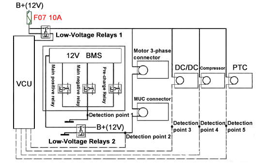
In the figure below, the thick solid line indicates 12V low-voltage power line circuit, and the dotted line is the HVIL monitoring circuit.The HVIL monitoring circuit for high voltage appliances (including DC/DC, compressor, PTC) is controlled via the VCU.The control pins of the VCU are directly connected to the low-voltage control terminals of the relays.The low-voltage control outputs of the three high-voltage relays inside the battery box are directly overridden via test point 1.Test point 1 monitors the operation of the emergency power-off circuit.The HVIL control circuit of the motor and MCU is connected directly to the control coil of low-voltage relay 2, with the other end directly overridden.
HVIL monitoring loop scheme 1
The specific working principle is as follows.
When there is an emergency power failure, detection point 1 sends the information to BMS, which directly disconnects the three high-voltage relays. The BMS directly disconnects the three high-voltage relays.
When the motor and MCU are well connected, the low-voltage relay 2 coil is switched on and the BMS works normally.
When the motor and MCU are not connected properly, the BMS is disconnected by controlling the coil of low-voltage relay 2.
Detection points 3, 4 and 5 detect the connection of DC/DC, compressor and PTC respectively and send them to VCU.
In this scheme, the BMS is linked to the motor and motor controller through relay 2.However, VCU needs to close and split the main circuit relay through the BMS.
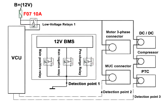
CASE 2
The thick solid line in the figure indicates the 12 V power line and the dotted line indicates the HVIL monitoring loop.Compared to scheme 1, the connections of motor, MCU connector, DC/DC, compressor, and PTC connector are detected by VCU.
HVIL monitoring loop scheme 2
The specific working principle is as follows.
When there is an emergency power failure, detection point 1 sends the information to BMS, which directly disconnects the three high-voltage relays. The BMS directly disconnects the three high-voltage relays.
The connection of motor and MCU is detected by detection point 2 and sent to VCU.
The connection of DC/DC, compressor and PTC in series is detected by test point 3 and sent to VCU.
If any connector is not connected properly, the VCU detects the result and controls the BMS, so that the BMS controls the high voltage relay to disconnect the power.
It is easy to see that in a high voltage interlock circuit, to know exactly which electrical’s connector has failed, a separate HVIL circuit needs to be designed for this electrical. If not exactly necessary, it is preferable to install correlated electrics in the same HVIL to simplify control.
Yes, High Voltage Interlock Loop (HVIL) cables often use shielding. The HVIL system is designed to ensure safety by detecting the connection and disconnection of high-voltage circuits in electric vehicles, and it is crucial that this system is reliable and free from interference.
The shielding in a cable is designed to reduce the electromagnetic interference (EMI) that can be picked up by the cable. EMI can come from many sources, including the high-voltage circuits that the HVIL system is monitoring. If this interference were to cause a false signal in the HVIL system, it could lead to unsafe conditions. Therefore, to ensure the reliability of the HVIL system, the cables used often include a shield layer.
Hi, thanks for your comment. HVIL signal pins are embedded inside of MSD. The HVIL is a feature built into the MSD, not a completely separate component. You can think of the MSD as a main safety switch, and the HVIL as a small security sensor inside it. When you start to pull out the MSD, the HVIL circuit disconnects first. This sends a signal to the system to cut the high-voltage power before the main contacts of the MSD are fully separated, preventing dangerous electrical sparks.


please send me quotation for hvil connector DC for panel and cable 1000v 500 amper
Thank you for your inquiry. Our sales team will be in touch with you shortly to discuss your requirements and provide further assistance.
Hi, is there any HVIL cable will use the shielding?
Yes, High Voltage Interlock Loop (HVIL) cables often use shielding. The HVIL system is designed to ensure safety by detecting the connection and disconnection of high-voltage circuits in electric vehicles, and it is crucial that this system is reliable and free from interference.
The shielding in a cable is designed to reduce the electromagnetic interference (EMI) that can be picked up by the cable. EMI can come from many sources, including the high-voltage circuits that the HVIL system is monitoring. If this interference were to cause a false signal in the HVIL system, it could lead to unsafe conditions. Therefore, to ensure the reliability of the HVIL system, the cables used often include a shield layer.
Is the HVIL part of the MSD, or are the HVIL and MSD two completely separate components?
Hi, thanks for your comment. HVIL signal pins are embedded inside of MSD. The HVIL is a feature built into the MSD, not a completely separate component. You can think of the MSD as a main safety switch, and the HVIL as a small security sensor inside it. When you start to pull out the MSD, the HVIL circuit disconnects first. This sends a signal to the system to cut the high-voltage power before the main contacts of the MSD are fully separated, preventing dangerous electrical sparks.