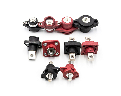
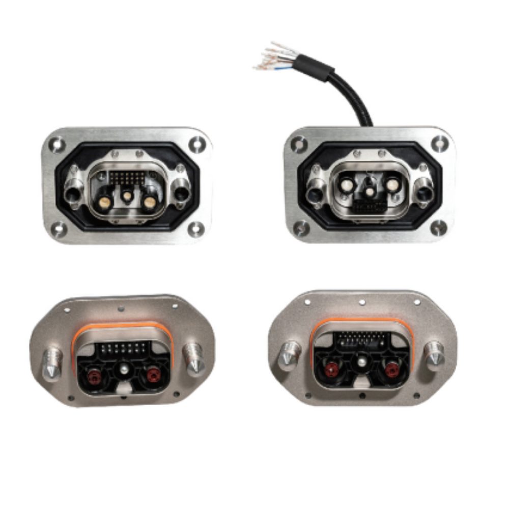
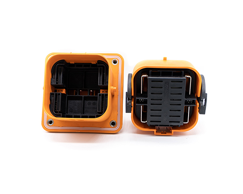
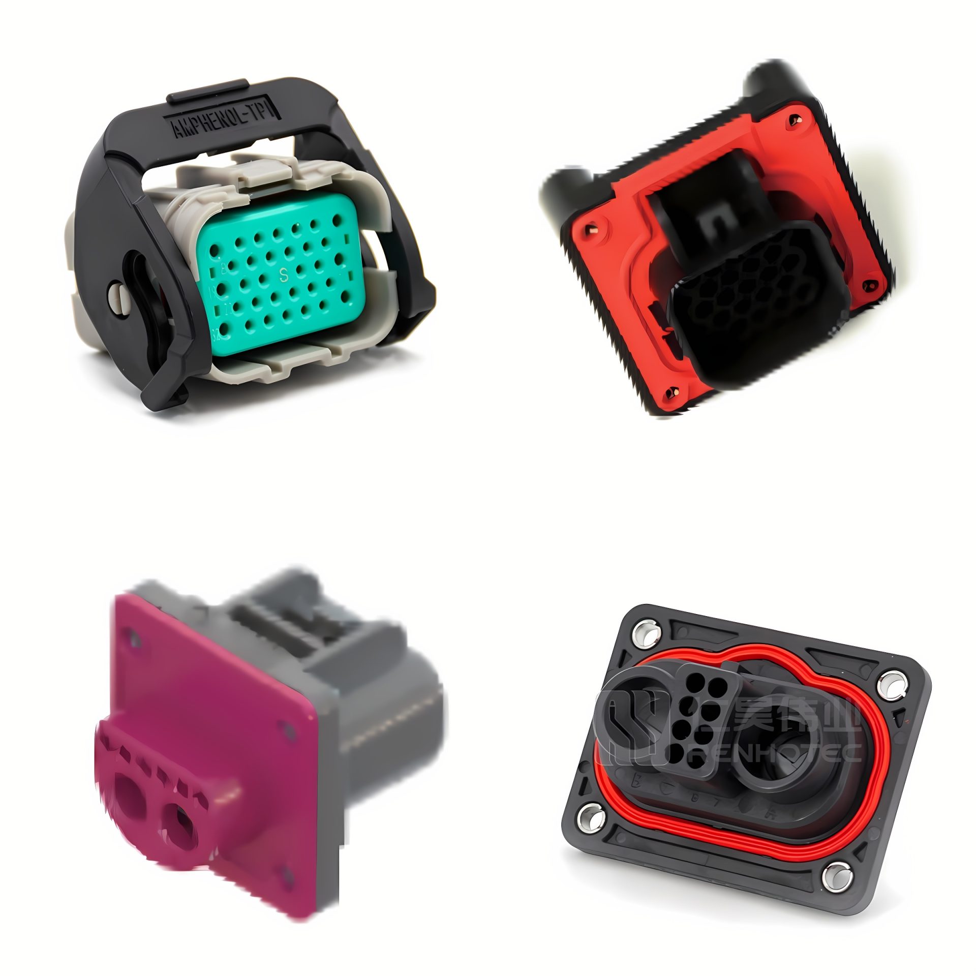
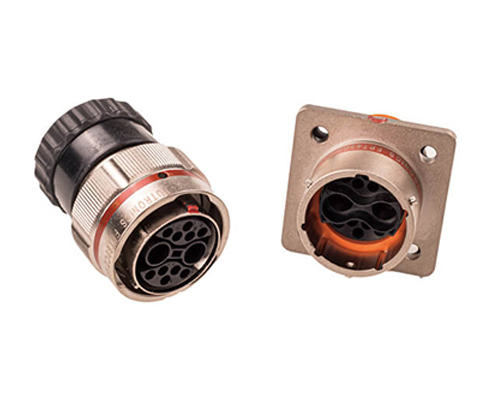
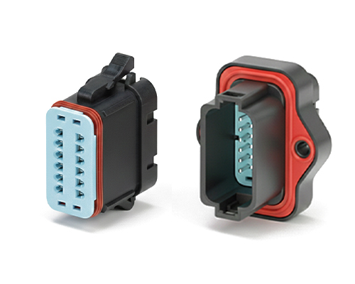
The Rectangular Connector is widely used in aerospace, medical instruments, consumer electronics (such as computers, TVs, game consoles, etc.), industrial control equipment, communication equipment, and automotive electronics. With its reliable connection performance, diverse specifications, and relatively convenient plug-in and unplug operations, it has become an indispensable component in various electronic and electrical applications.
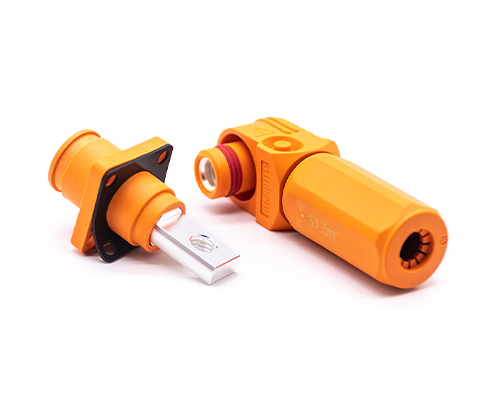
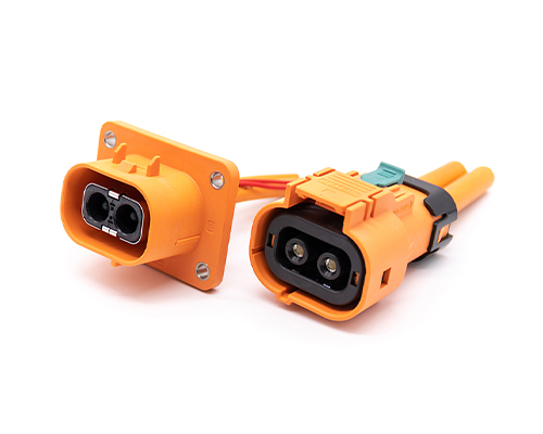
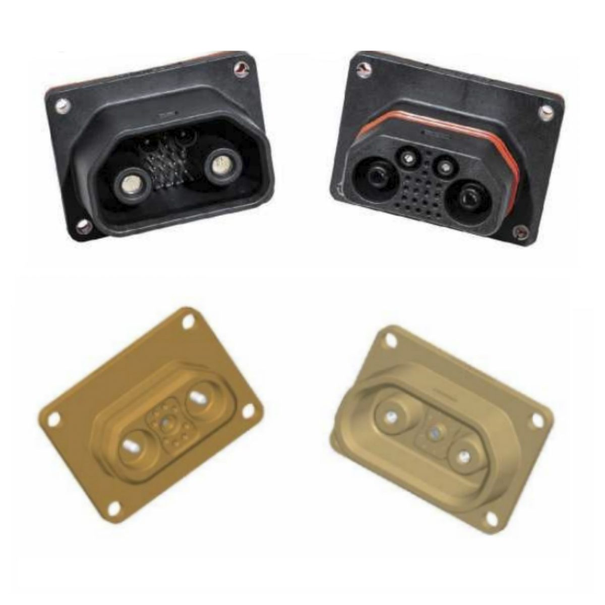
High Voltage Connectors are widely used in EV power systems, renewable energy installations, and industrial high-voltage circuits. Renhotec’s series drives the building of efficient, safe, and sustainable electrical ecosystems, meeting current technological demands.
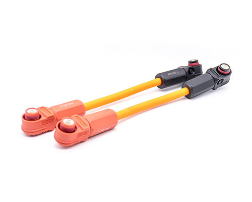
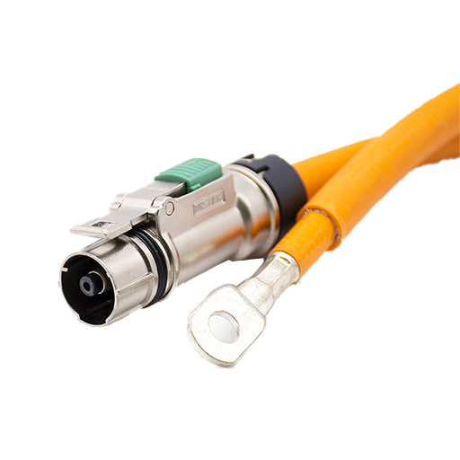
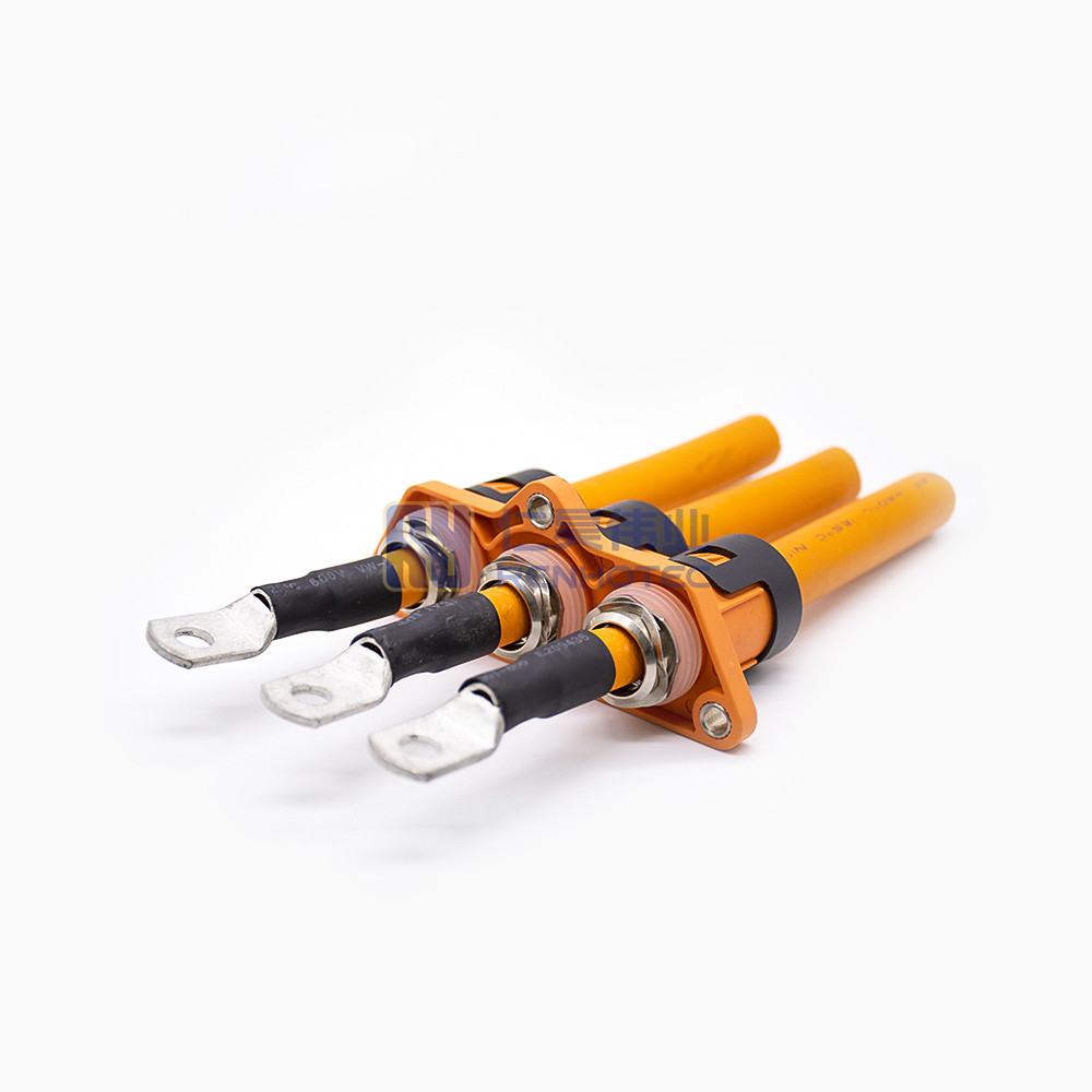
Renhotec EV Cable, crafted with top-notch conductive materials and meticulously engineered insulation, showcases outstanding impedance control and voltage-withstanding properties. Its design combines flexibility and durability to meet a wide array of installation needs. This cable is widely utilized in grid interconnections, large-scale industrial power supply systems, and high-voltage renewable energy projects, enabling smooth and efficient power transmission.
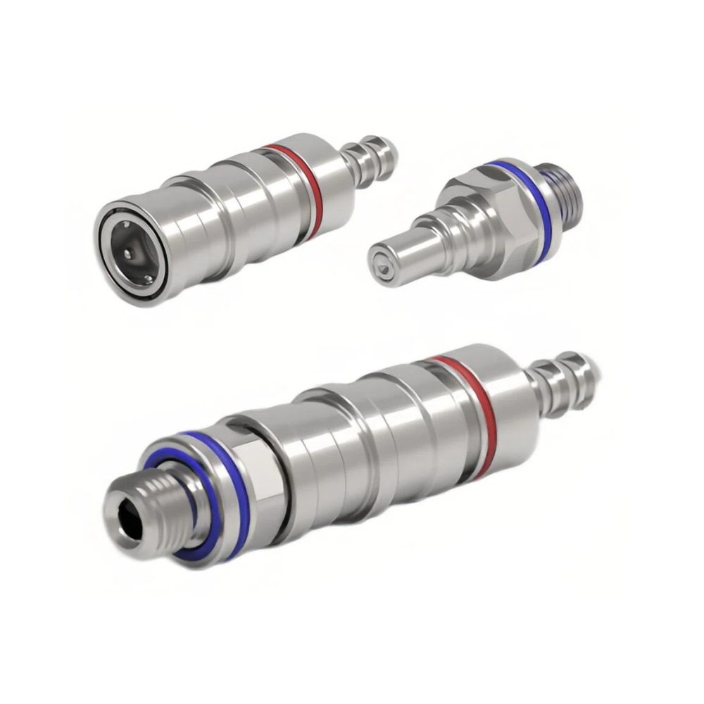
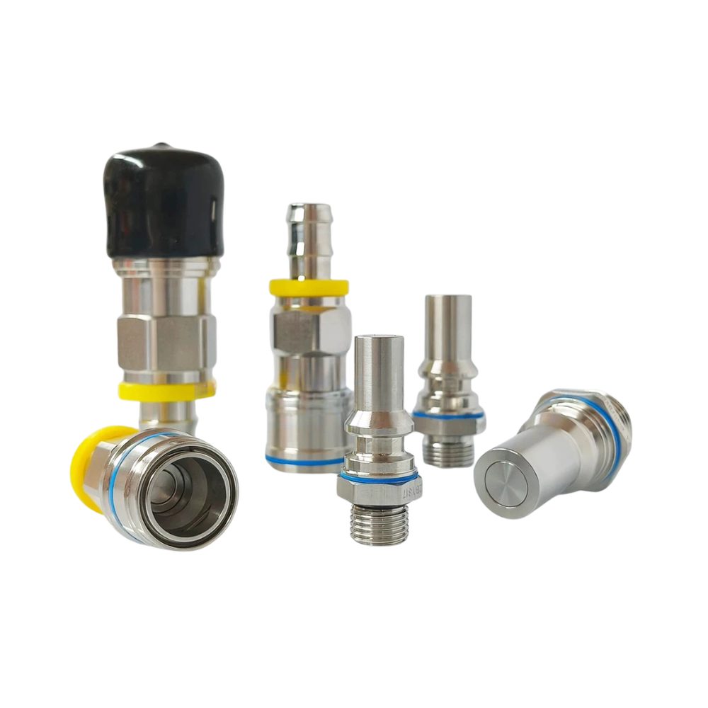
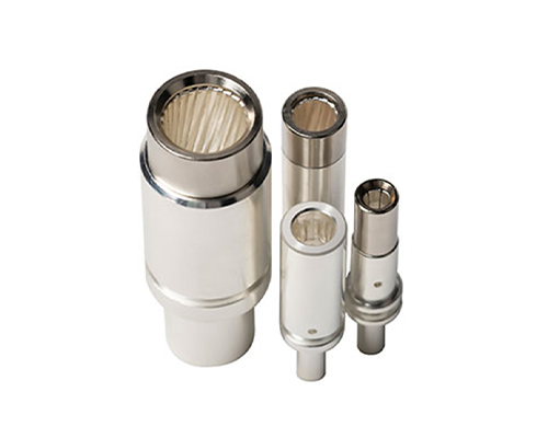
Renhotec, as a professional supplier, offers a comprehensive range of these Signal Transmission Connector products. Whether it is the high-reliability applications of the metal series or the wide adaptability of the plastic series in consumer electronic products, Renhotec can provide customers with high-quality options to meet the diverse requirements of signal transmission connections in different industries and scenarios.
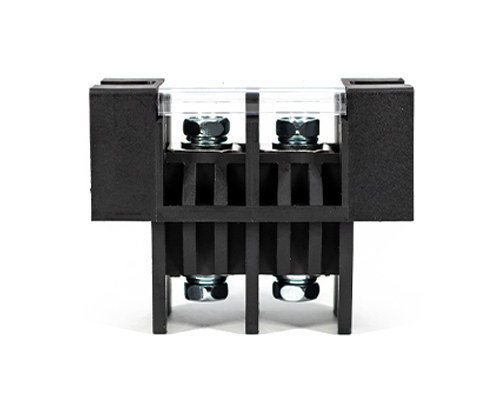
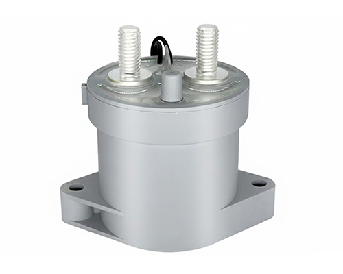
Renhotec, active in electrical components, offers High Voltage DC Contactors in Epoxy Resin Sealing and Ceramic Sealing variants, with a 20A – 1000A current range. The Epoxy Resin Sealing one is cost-effective and protective. The Ceramic Sealing variant excels in thermal stability and insulation. They’re widely used in EV charging, renewable energy grid, and industrial high-voltage DC power distribution for reliable circuit control and current interruption, providing comprehensive solutions for multiple sectors.
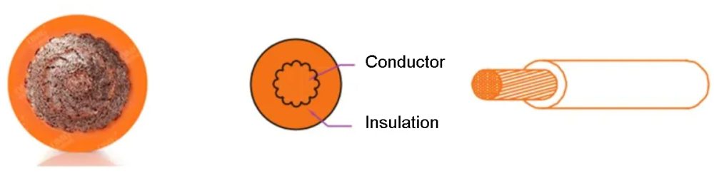
The wire can be divided into single-core wire and multi-core wire according to the process characteristics. The difference is that multi-core wires are composed of multiple single-core wires. In essence, the electrical performance parameters and structural size parameters of each single-core wire and single-core wire is no different.
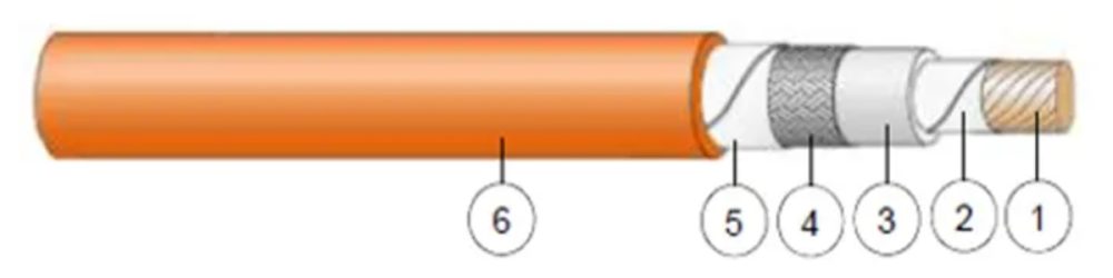
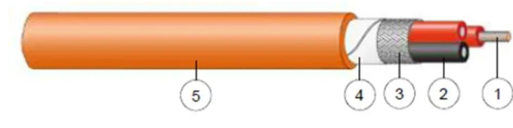
Single-core With Shielding WireMulti-core With Shielding Wire
High voltage wires can also be distinguished as unshielded wires and shielded wires according to whether they have a shielding layer or not.
In addition to single-core shielded wire, single-core unshielded high-voltage wire, multi-core shielded high-voltage wire, multi-core unshielded high-voltage wire, these four arrangements of the combination of the wire. We can also classify high-voltage wires according to the following characteristics.
Characteristics
Classification
Core cross-sectional area
0.13mm²-120mm²
Core material
High-voltage conductors with copper cores
High-voltage conductors with aluminum cores
Insulation thickness
Thin-walled high-voltage conductors
Standard wall thickness
Thick-walled high-voltage conductors
Temperature resistance grade
Standard high voltage conductor 85℃-125℃
Super high temperature resistant grade high voltage conductor 250℃
2.Composition of the High-voltage Wire
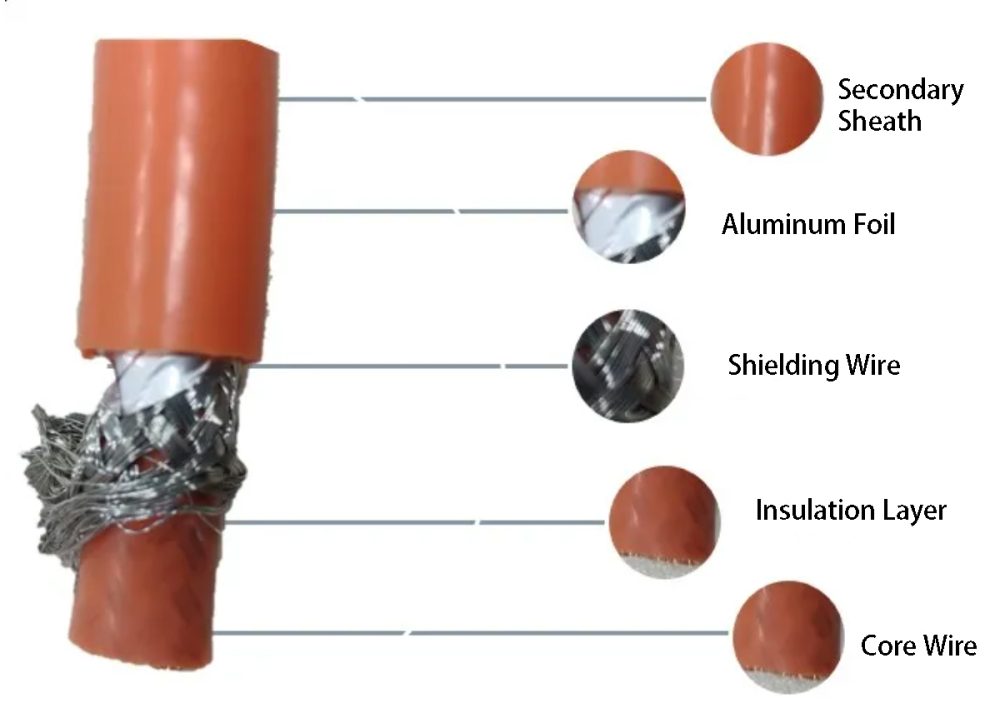
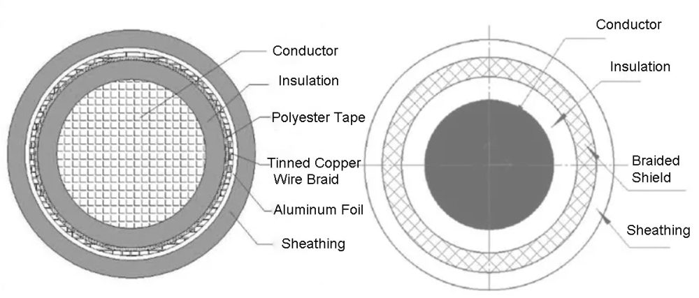
Cut the high-voltage line from the outside to the inside, and you can see the following structural diagram.
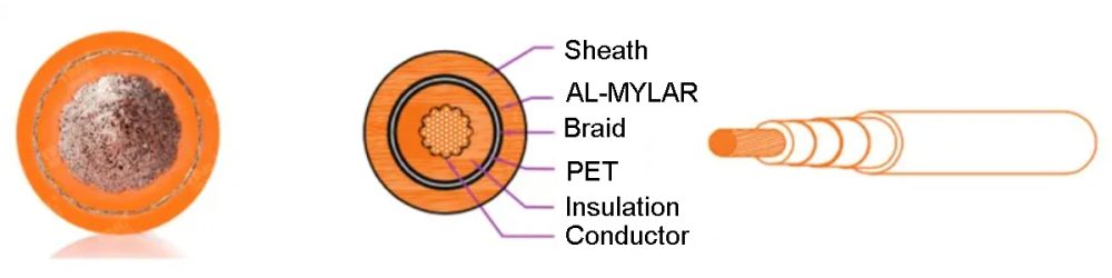
The high-voltage conductor consists of secondary sheath (also called outer insulation layer), aluminum foil, shielding braid, inner insulation layer and core wire (conductor).
Some of the high-voltage wires have a layer of wrapping tape between the shielding layer and the secondary sheath. The role of the wrap tape is to facilitate the production of crimped terminals for the insulation layer to be peeled off, similar to the non-woven material, wrapped around the wire to play a certain role in isolation.
The main structure of the high-voltage wire size parameters are also around these layers of elements, including the outer diameter of the secondary sheath, the diameter of the inner insulation layer, conductor diameter, single copper wire diameter, the number of copper wire roots, etc.
Anatomy of a High-voltage Wire
3.The Role of the Insulation Layer of High-voltage Wires
(1) Insulation: Prevents contact between the core wire and other external conductors, resulting in a short circuit in the circuit.
(2) Protection of the core wire: to avoid abrasion of the internal core wire by liquids and external devices.
(3) IP protection: including dustproof, waterproof, and anti-touch (human body protection).
(4) Parts arrangement: Provide certain flexibility for the high-voltage harness to facilitate the arrangement of the high-voltage harness on the body of the vehicle.
(5) Anti-scratch abrasion, flame retardant and other special roles in weather resistance and reliability.
4.High-voltage Wire Insulation Material Performance
Unlike low-voltage conductors, which have only an outer insulation layer, high-voltage conductors have both inner and outer insulation layers, and the outer insulation layer is often referred to as the secondary sheath. The inner and outer insulation layers are generally made of XLPO (cross-linked polyolefin), SIR (silicone rubber) and TPE (thermoplastic elastomer).
Project
SIR
XLPO
TPE
Difference Description
Temperature class
180℃~200℃
125℃-150℃
125℃
One of the main characteristics of silicone is its good heat resistance. The pressure deformation in high temperature environment (~150℃) is about 10%, which is suitable for application in front compartment or high temperature requirement. Temperature resistance level: SIR>XLPO>TPE (where TPE is a thermoplastic material, there is a risk of cracking in long-term use.)
Hardness
60~70 ShA
75~95 ShA
80~95 ShA
The second characteristic of silicone rubber is its softness and smaller bending radius. For shielded wires, the advantages of using silicone rubber are more obvious. Compared to TPE and XLPO (cross-linked polyolefin), which have the risk of cracking when the bending radius is small, silicone rubber is more stable in long-term operation. Minimum bending radius: SIR < TPE < XLPO.
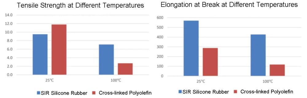
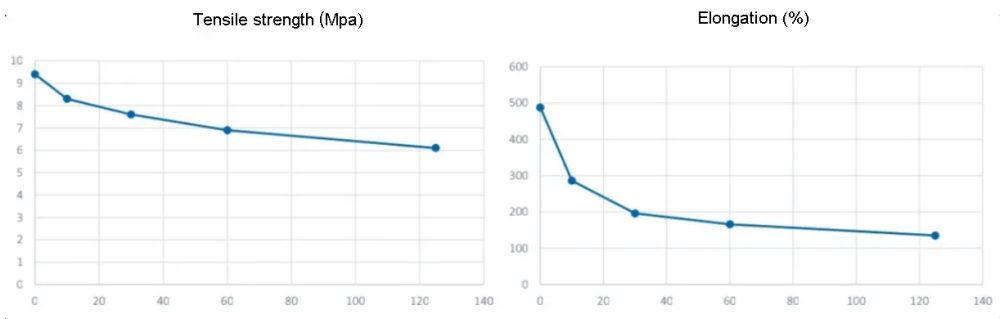
Tensile strength
8~10
10.3
10.3
The strength of XLPO material is better than silicone. Strength level: XLPO > TPE > SIR.
Elongation at break
400~600
200
400
The elongation at break of silicone is better than that of XLPO, and the elongation retention value after short-term aging is better than 100% than that of XLPO material. Elongation level: SIR > TPE > XLPO.
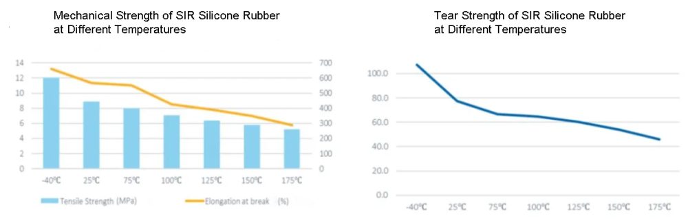
Tear strength
10~25
15
15
The hardness of silicone rubber is more difficult to change through changes in the constituent materials, so silicone rubber produced between different manufacturers is basically equivalent in hardness. The tear strength of ordinary silicone is about 10, and the tearing of high tear-resistant silicone pants can reach 25N/mm, related to the level of temperature resistance, flame retardant level, etc.
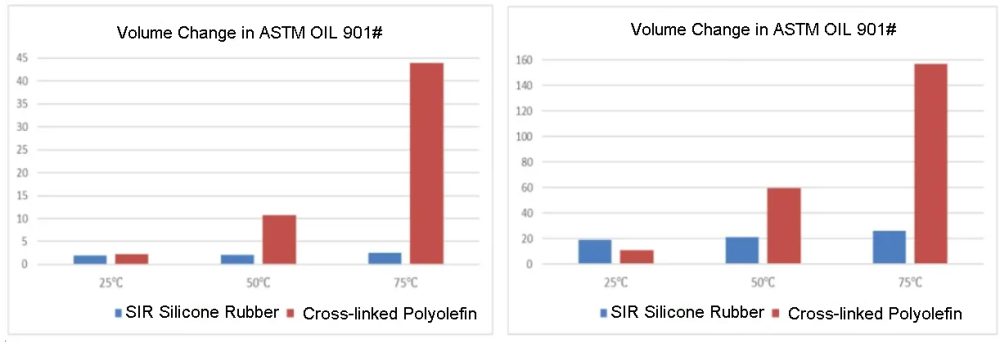
Gasoline resistance change rate
<40
<15
<15
Silicone rubber can pass all liquid tests except for gasoline immersion. Its gasoline resistance level is poor, with a change rate of about 40%, but this is not a key indicator for electric vehicles. Gasoline resistance level: XLPO > TPE > SIR.
Flame retardant level
VO
VO
VO
XLPO material has better flame resistance than silicone, but both can pass the finished flame resistance test. Flame retardant level: XLPO>SIR>TPE.
Specific gravity
1.15~1.2
1.45
1.15
The specific gravity of silicone is relatively small, which is beneficial to the lightweight design of the whole vehicle. Specific gravity value: TPE<SIR<XLPO.
Short-term aging
205℃*10d 225℃*10d
150℃*10d 175℃*10d
150℃*10d
Excellent aging performance of silicone with high temperature resistance grade. Aging performance: SIR>XLPO>TPE.
Long-term aging
180℃*3000h 200℃*3000h
125℃ *3000d 150℃
125℃ *3000h
Excellent aging performance of silicone with high temperature resistance grade. Aging performance: SIR>XLPO>TPE.
Combined with the above comparison table of the characteristics of the three materials, we can draw the difference between the three materials at the application level:
XLPO has a wider range of applications, and the part in contact with the motor, the service life is weak, TPE material is mostly applicable to large-size wire and communication conductors.
SIR silicone rubber in addition to the above characteristics, but also has a better sealing, in high temperature and high pressure, small deformation, suitable for the need for high temperature resistance, small installation space, small bending radius, as the electric vehicle high-voltage wire insulation layer material, is more than suitable.
Tensile Strength and Elongation at Break of SIR Silicone Rubber at Different TemperaturesMechanical Strength and Tear Strength of SIR Silicone Rubber at Different TemperaturesVolume Change Rate of SIR Silicone Rubber in Different Oils for Oil Resistance TestPerformance of SIR Silicone Rubber in Aging Test at 200°C and 3000 Hours
5.The Role of High-voltage Wire Shielding Layer
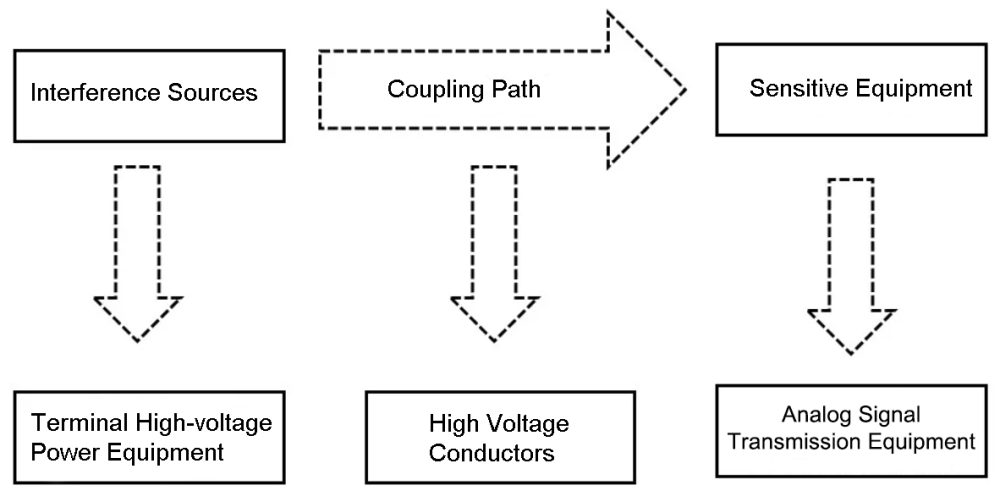
Electric vehicle high-voltage cables are subjected to higher voltage (rated voltage up to 600V), higher current (rated current up to 600A) and stronger electromagnetic radiation. Although the high-voltage conductor itself does not generate a lot of electromagnetic interference, but the coupling voltage and coupling current of the conductor basically come from the terminal connected to the conductor, that is, the high-voltage appliances.
Both ends of the wire, that is, the terminal crimp, concentrated electromagnetic interference. Therefore, the vast majority of high-voltage conductors are currently designed with shielding structures to resist electromagnetic interference.
The coaxial structure is used, using the joint action of the inner and outer conductors (shield). The magnetic field inside the conductor is distributed in concentric circles, while the electric field points from the inner conductor and stops at the outer conductor, so that the external electromagnetic field around the cable is zero. It not only shields electromagnetic radiation, but also eliminates coupling voltage and coupling current in this area.
High-voltage wire harness parts are required to meet the requirements of ISO 14572 in the electromagnetic compatibility (EMC) test of the whole vehicle. Transfer impedance ≤ 31mΩ/m, shielding attenuation ≥ 70dB, to meet the EMC requirements of the whole vehicle.
High Voltage Conductors in Electromagnetic Interference
6.Composition of Shielding for High Voltage Wires
Two Different Forms of Shielding Layer Composition
The shielding layer of high-voltage conductors is divided into a shielding wire braid layer and an aluminum foil layer, and the conventional shielding layer structure is as follows.
①Only shield wire braid layer.
②Shield wire braid (near the inner insulation layer) + aluminum foil layer (near the outer insulation layer).
③ Aluminum foil layer (near the inner insulation layer) + shielding wire braid layer (near the outer insulation layer) three states.
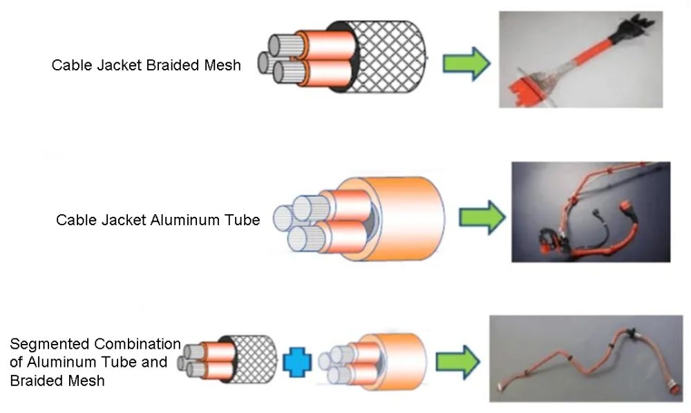
Of course, there are also some high-voltage conductors that are protected by EMC in the form of braided mesh, aluminum tubes or a combination of both.
Different Forms of Shield Composition
(1) Shielding Wire Braid Layer
The essence of the shielding wire braid is a wire with a metal braid sheath, which acts as a low-frequency shield. It is mainly made of 0.2mm² or 0.15mm² tinned copper wire braid, the preparation density must reach 90% or more.
Shielding wire diameter, braiding angle, the number of wires per spindle and braiding machine tension are several important parameters of the braided shielding wire.
Conventional shielding wire diameter of 0.2mm² and 0.15mm² two specifications. The thicker the wire diameter, the better the shielding effect
Host manufacturers and high-voltage wire manufacturers generally define the shield preparation angle in the range of 50° to 60°, in which the processing efficiency is highest.
The number of shielding wires per spindle is determined by each wire manufacturer. The more shielding wires per spindle, the larger the braiding pitch and the lower the relative tension.
(2) Aluminum Foil Layer
Aluminum foil is generally used aluminum-plastic composite tape, mainly composed of aluminum, high-temperature coking glue and PET material with a temperature resistance class of 80℃. Its role is high frequency shielding.
The cladding force of the aluminum foil wrapped around the insulation layer inside the high-voltage conductor is preset by the manufacturing machine. The exact size varies depending on the supplier of the conductor.
The vast majority of high-voltage conductors have the aluminum foil layer on the outside of the braid, and a small number of high-voltage conductors have the aluminum foil layer on the inside of the braid. Either way, the foil layer should be in contact with the braid and conductive.
The shield needs to be grounded to direct the external interference signals to earth, thus avoiding interference signals into the inner wire core.
It is important to note that the shield layer does not allow multiple points of grounding. Because there will be potential differences between different grounding points. If the shield multi-point grounding, will form a current in the shield layer, induction to the wire to form a current, induction to the signal line to form interference, not only can not play a shielding role, but to cause interference.
In the high-voltage wire factory, whether it is aluminum foil or woven shield, are in an unbroken state (i.e., complete wrapped in the wire insulation layer). Shield breaking work (including the cutting of aluminum foil and shielding wire expansion) is generally completed by the high-voltage harness assembly supplier, before the wire and connector connection installation.
7.Magnetic Ring
The connection between high-voltage harness and high-voltage connector will receive more serious EMC interference, so the interface of each high-voltage connector needs to use shielding treatment. For example, the front and rear motor interfaces are shielded with the electrical box rail crimp, and the controller and battery box connectors are shielded with structural parts.
It is a common and efficient practice to add magnetic rings to high-voltage harnesses and high-voltage equipment.
Magnetic ring is a ring-shaped magnetic conductor, magnetic ring is a common anti-interference original in electronic circuits, for high-frequency noise has a very good suppression effect.
(1)Magnetic Ring Material
According to the frequency of the interference to be suppressed, choose different permeability of ferrite materials. The higher the permeability of ferrite materials, the greater the impedance of low frequency, the smaller the impedance of high aluminum.
(2)Magnetic Ring Performance
The effect of the magnetic ring is related to the circuit impedance, the lower the impedance of the circuit, the better the filtering effect of the magnetic ring. The greater the impedance of the ferrite material, the better the filtering effect. When capacitive filter connectors are installed at both ends of the conductor, the impedance is very low and the effect of the magnetic ring is more obvious.
The installation position of the magnetic ring is generally as close as possible to the source of interference. For the high-voltage system of the high-voltage harness, the magnetic ring should be as close as possible to the motor, controller high-voltage wire import and export.
The larger the difference between the inner and outer diameter of the magnetic ring, the longer the axial direction, the greater the impedance. The inner diameter must be wrapped tightly around the wire. Therefore, to obtain a large attenuation, under the premise that the inner diameter of the magnetic ring wrapped tightly around the wire, try to use a larger volume of the magnetic ring.
Increasing the number of magnetic rings on the cable can increase the low frequency impedance. However, due to the increase of parasitic capacitance, the high-frequency impedance will decrease accordingly.
8.Conclusion
This article is about the classification and composition of high-voltage wires, as well as to the high-voltage wire insulation and shielding layer composition. If you are interested in the product, or have any questions and suggestions, welcome to contact us, our professional team will be happy to serve you.
One thought on “High-voltage Wire Harness Components – Wires”
Mia Evans says:
I find it interesting when you said that high voltage wires can be categorized as shielded and non-shielded materials depending on the layer they might or might not have. It seems like there are different parts to consider and various options when it comes to needing those types of materials for your operations or facility. The best thing to probably do is to actually have custom wholesale wire harness instead to ensure that it can cater to your needs which make them safe to use by your workers.


I find it interesting when you said that high voltage wires can be categorized as shielded and non-shielded materials depending on the layer they might or might not have. It seems like there are different parts to consider and various options when it comes to needing those types of materials for your operations or facility. The best thing to probably do is to actually have custom wholesale wire harness instead to ensure that it can cater to your needs which make them safe to use by your workers.