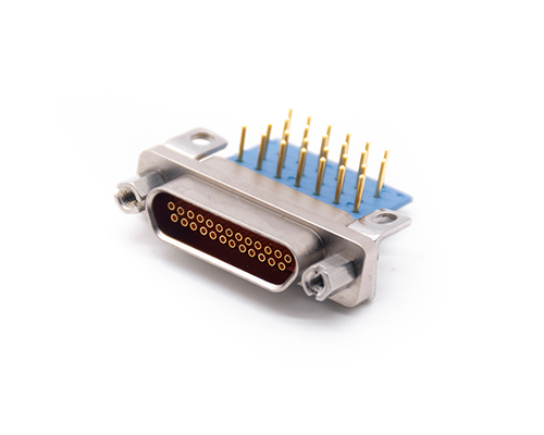
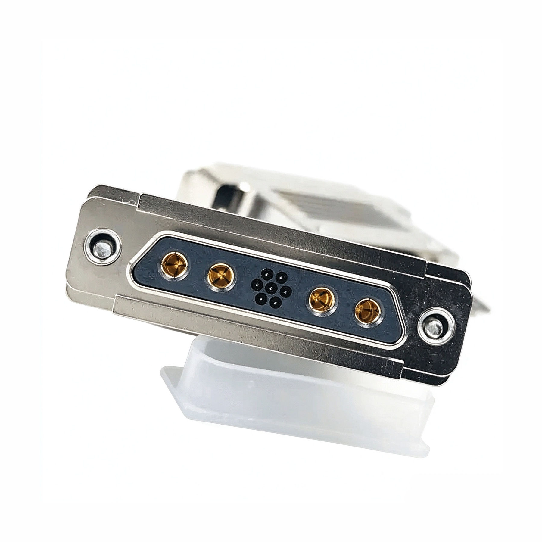
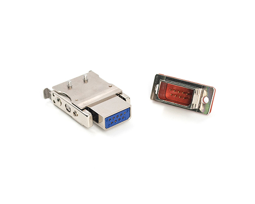
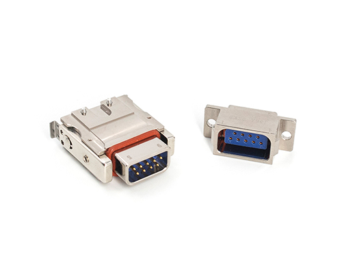
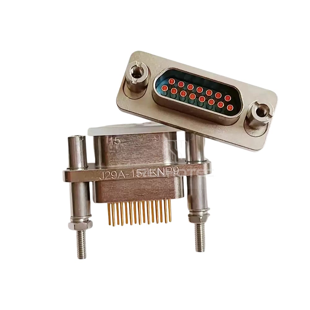
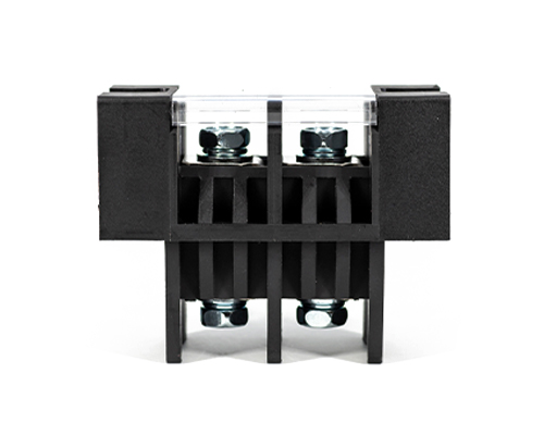
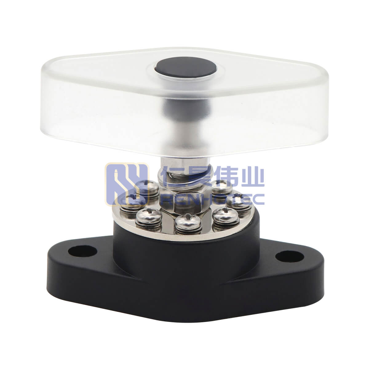
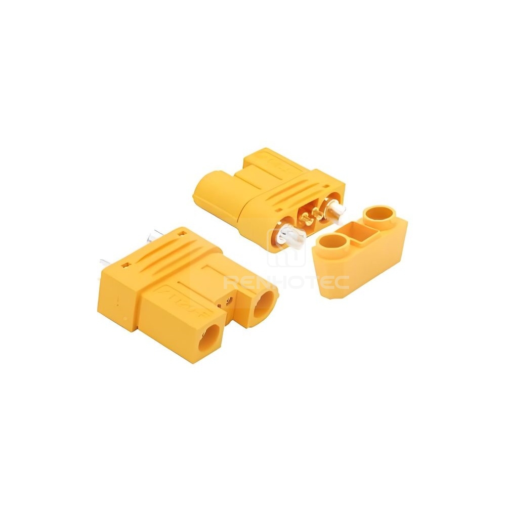
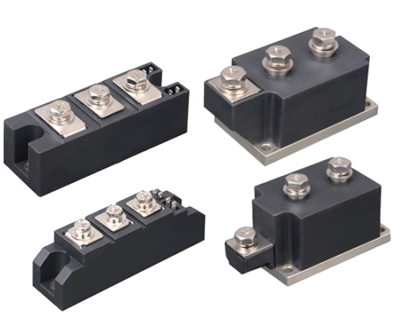
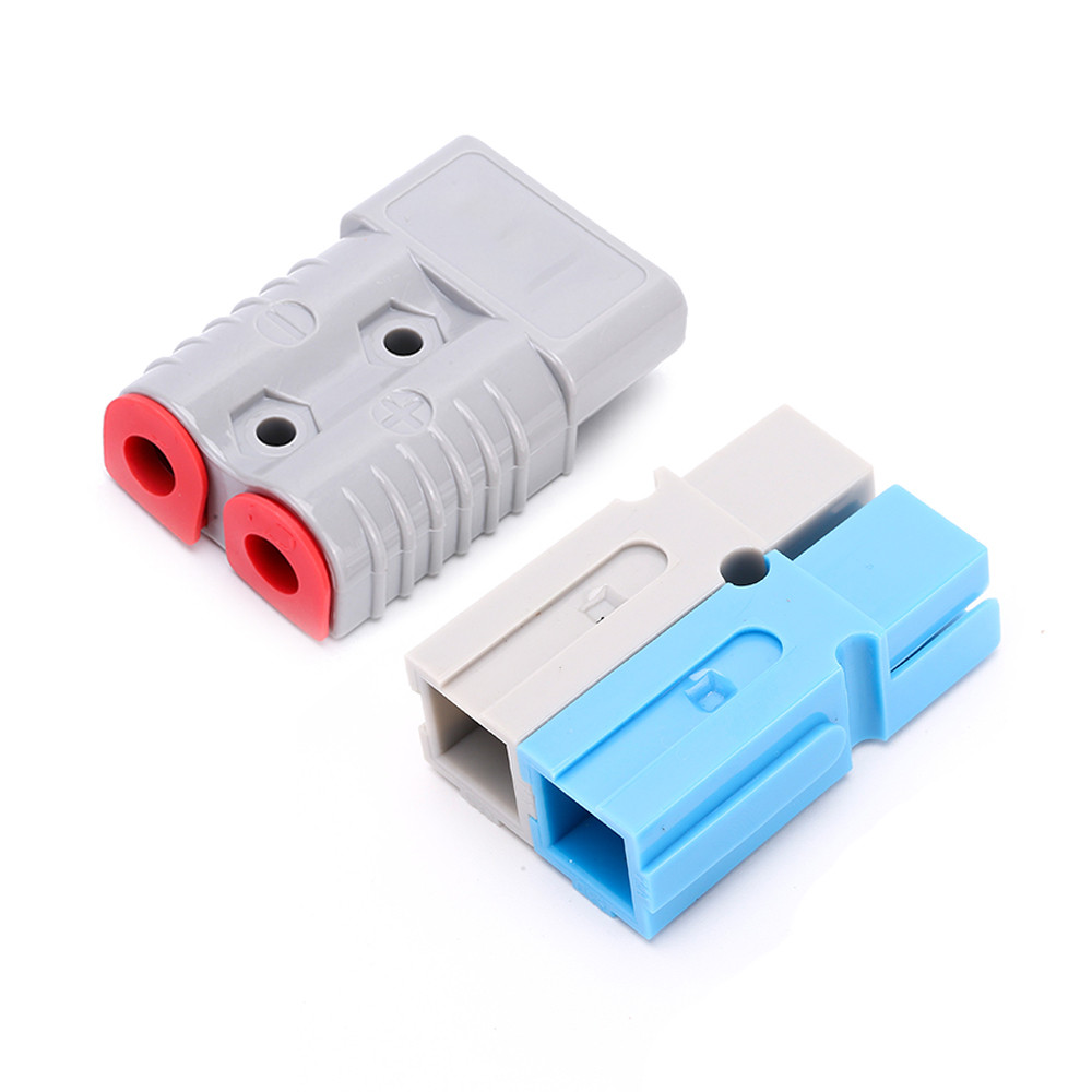
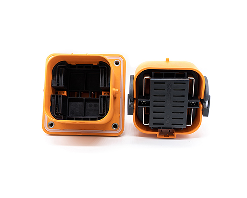
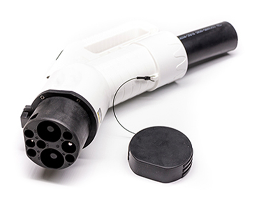
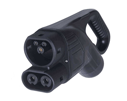
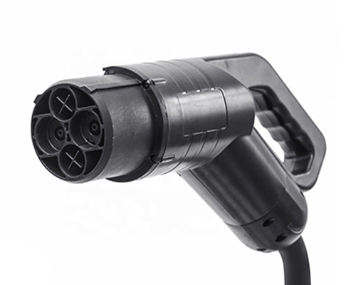
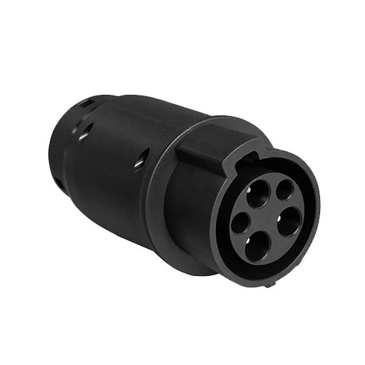
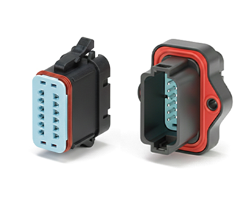
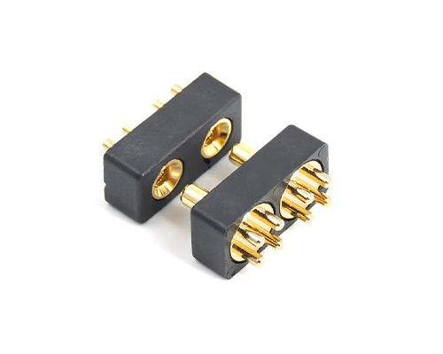
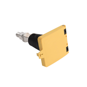
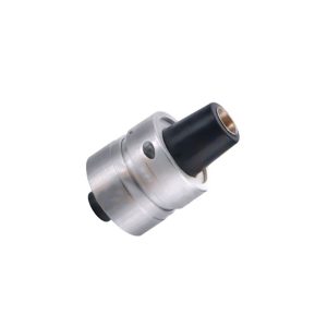
The Rectangular Connector is widely used in aerospace, medical instruments, consumer electronics (such as computers, TVs, game consoles, etc.), industrial control equipment, communication equipment, and automotive electronics. With its reliable connection performance, diverse specifications, and relatively convenient plug-in and unplug operations, it has become an indispensable component in various electronic and electrical applications.
J30J General Connectors and Cable Assemblies
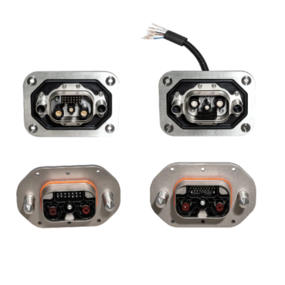
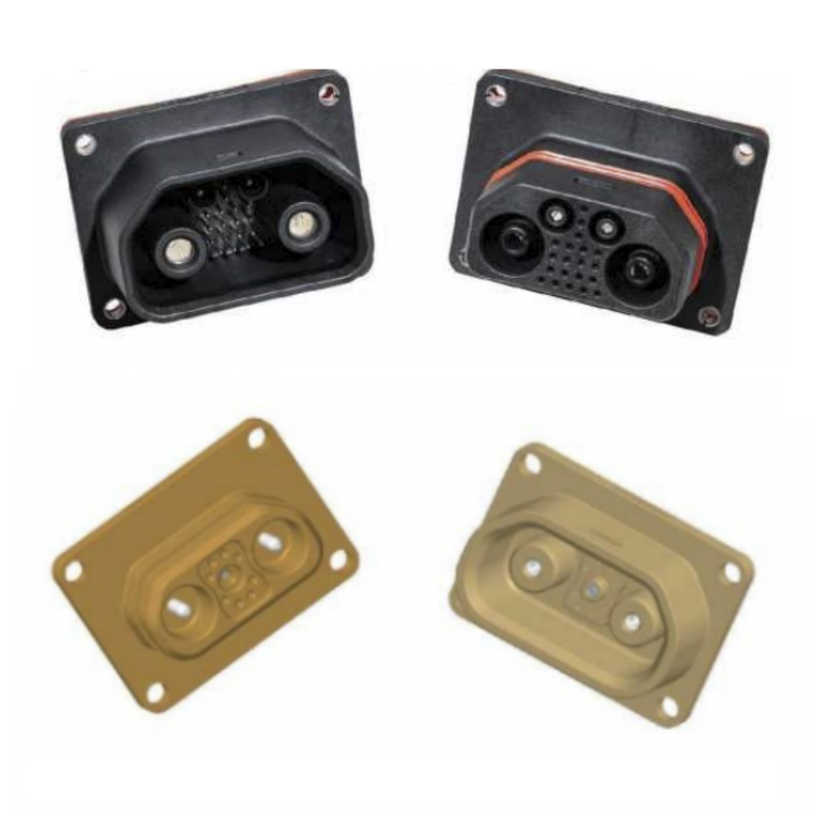
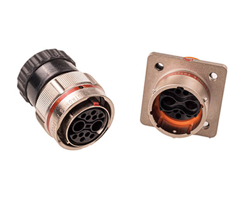
J30J Mixed Current (Hybrid) Connectors and Cable Assemblies
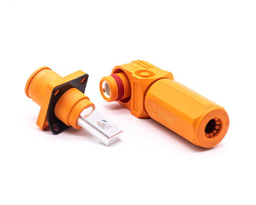
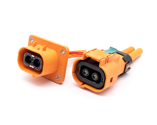
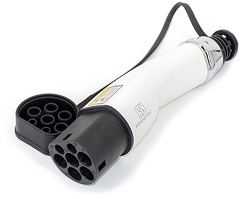
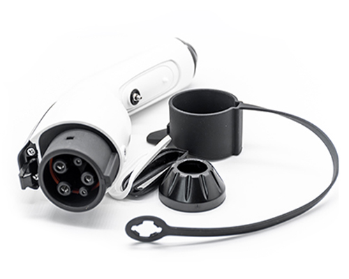
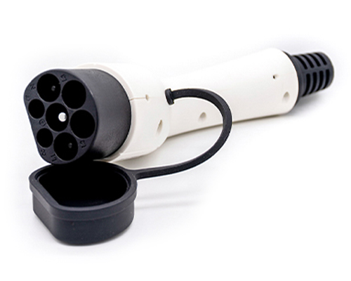
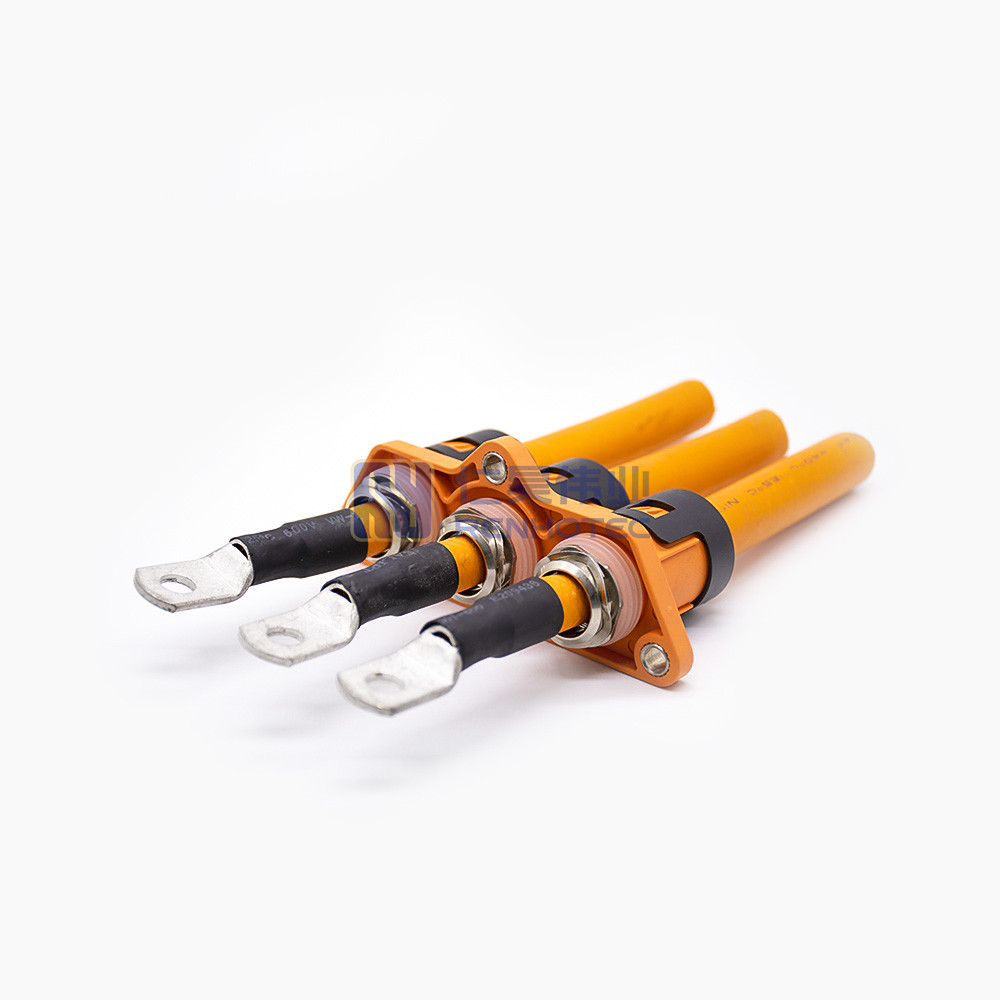
High Voltage Connectors are widely used in EV power systems, renewable energy installations, and industrial high-voltage circuits. Renhotec’s series drives the building of efficient, safe, and sustainable electrical ecosystems, meeting current technological demands.
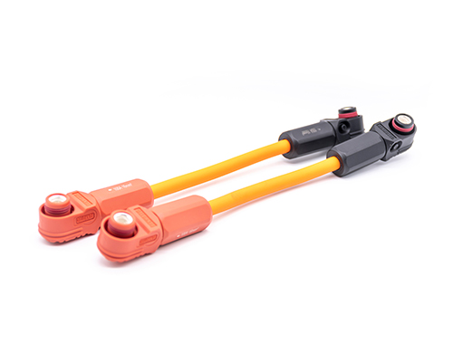
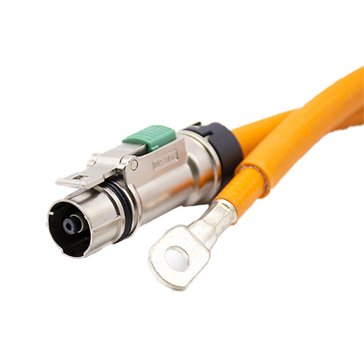
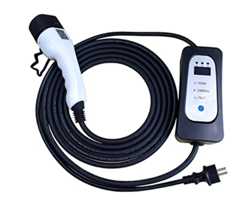
Renhotec EV Cable, crafted with top-notch conductive materials and meticulously engineered insulation, showcases outstanding impedance control and voltage-withstanding properties. Its design combines flexibility and durability to meet a wide array of installation needs. This cable is widely utilized in grid interconnections, large-scale industrial power supply systems, and high-voltage renewable energy projects, enabling smooth and efficient power transmission.
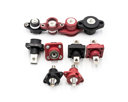
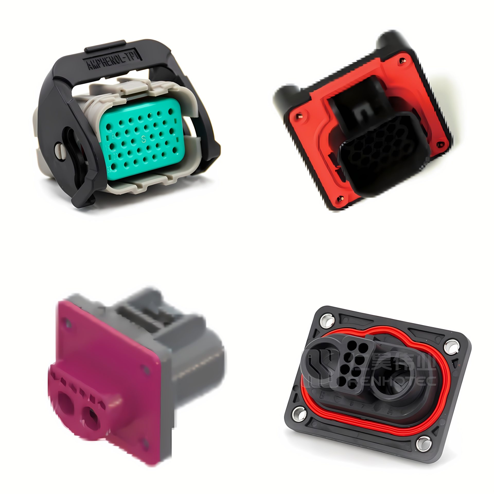
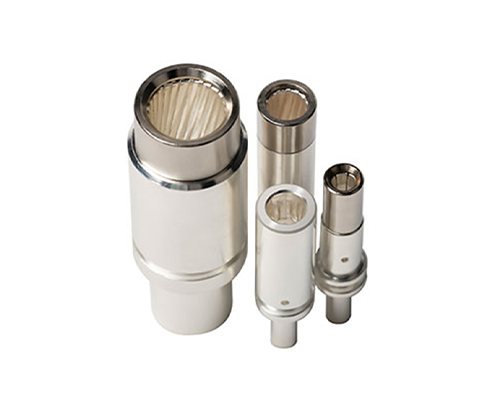
Renhotec, as a professional supplier, offers a comprehensive range of these Signal Transmission Connector products. Whether it is the high-reliability applications of the metal series or the wide adaptability of the plastic series in consumer electronic products, Renhotec can provide customers with high-quality options to meet the diverse requirements of signal transmission connections in different industries and scenarios.
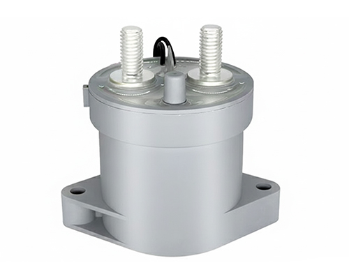
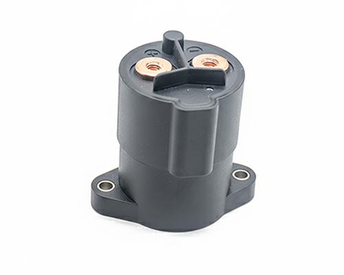
Renhotec, active in electrical components, offers High Voltage DC Contactors in Epoxy Resin Sealing and Ceramic Sealing variants, with a 20A – 1000A current range. The Epoxy Resin Sealing one is cost-effective and protective. The Ceramic Sealing variant excels in thermal stability and insulation. They’re widely used in EV charging, renewable energy grid, and industrial high-voltage DC power distribution for reliable circuit control and current interruption, providing comprehensive solutions for multiple sectors.
How Many UQD Couplings Does an NVL72 Rack Need? A Two-Level Answer
NVIDIA publishes no quick-disconnect bill of materials for an NVL72 rack. Separate the two places coolant connections sit and the question has a usable answer. At the rack manifold, each tray presents one supply and one return disconnect. On Lenovo’s documented GB300 NVL72 implementation, 18 compute trays and 9 NVLink switch trays therefore account for 54 mated disconnect points, or 108 connector halves. Smaller fittings inside each tray link cold plates to an internal manifold; those are a different component class with no published count. What you can count is the tray-to-manifold interface; which standard, revision and size a rack uses is an OEM drawing question. Figures vary by OEM design; the sources behind the 54 figure are set out below.
One coupling here means one mated disconnect point: a plug, its socket and the seal between them. A supply-and-return loop needs two. The same hardware can be counted four ways: physical blind-mate blocks, fluid channels, mated disconnect points, or individual connector halves. A dual-channel blind-mate block may be one module, two channels and two mated points at once. Suppliers quote per half; engineers design per mated point. Put the unit into the RFQ or the BOM will be off by a factor of two.
We count mated disconnect points between a tray and the rack manifold, excluding CDU-side couplings, manifold-internal joints and permanent tube fittings. OEMs may use hand-mate, blind-mate or hybrid couplings at the tray edge; OCP UQD and UQDB define those interface families, not which one a rack ships with. Blind-mate alignment is a tolerance-stack question: ask the OEM for the allowable radial and angular offset and the supplier for the test evidence.
One physical blind-mate block can be two fluid channels, two mated disconnect points and four connector halves at the same time.
The Two Levels in One Rack
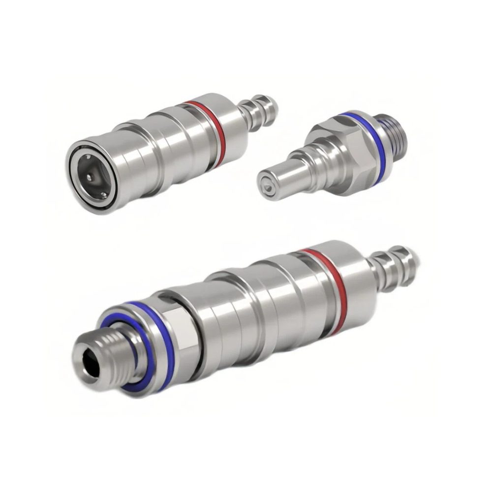
Rack-level tray-to-manifold quick disconnects sit at the tray edge; the internal fittings inside the tray are a different component class with no published count.
An NVL72 rack has two distinct liquid-cooling connection levels, and most quantity confusion comes from mixing them. The rack level is the serviceable break between a tray and the rack’s supply and return manifolds; it is the population counted here. The node level sits inside the compute tray, where cold plates connect to an internal distribution manifold. OCP UQD and UQDB cover the first interface family; the second is internal fittings and coolant interconnects, with type and quantity set by the OEM. Not every in-tray connection is documented as a quick disconnect. The two populations are not interchangeable and should not be counted together. Only the rack level is countable, and its tray count has to be confirmed from primary documentation.
Attribute
Rack level: tray to manifold
Node level: cold plate to internal manifold
Where it sits
Rear of each compute or switch tray, at the rack manifold
Inside the compute tray
Interface
Standardized hand-mate or blind-mate quick disconnects (OCP UQD / UQDB family); type, revision and size are OEM-specific
Internal fittings and coolant interconnects; type and quantity set by the OEM
What sets the count
Tray count and the supply/return arrangement
Cold-plate layout chosen by the OEM
Published quantity
Derivable from OEM tray documentation
Not published by NVIDIA
In scope here
Yes
Background only
Where the 54 Figure Comes From
Two document sets support that count: NVIDIA’s DGX GB Rack Scale Systems User Guide, which defines the reference architecture, and Lenovo’s GB300 NVL72 documentation, which describes one OEM implementation. The NVIDIA guide covers both GB200 and GB300 NVL72 with 18 1RU compute trays (2 Grace CPUs and 4 Blackwell GPUs each) and 9 1RU NVLink switch trays. It describes cold plates on the CPUs and GPUs, fans for networking and storage devices, and approximately 120 kW of rack power for that reference configuration. OEMs publish their own power budgets, and a liquid-cooled AI rack remains a hybrid thermal system.
The Lenovo pages go one level deeper. Its compute tray rear view labels exactly four items: coolant return, cable cartridge connectors, coolant supply, and busbar connector – one coolant inlet and one outlet per tray. Technical specifications list two liquid cooling loops and eight dual-rotor fans per tray. Removing an NVLink switch tray calls for two quick connect caps at its rear, so switch trays present coolant connections too even though the reference guide describes air-cooled networking devices; which components are liquid cooled is an OEM choice. None of these pages names an OCP interface type, revision or size – confirm that from the OEM drawings and QD schedule. Both document sets are linked in Sources and Standards below.
The arithmetic is short: 18 compute trays x 2 disconnects plus 9 switch trays x 2 equals 54 mated disconnect points, or 108 connector halves. That assumes one supply-and-return pair per tray, switch trays included. It is a baseline for one OEM implementation, not an NVL72 constant; ask the OEM for its QD-level schedule.
Why Cold-Plate Count Does Not Determine Rack-Level QD Count
GB200 and GB300 NVL72 share the 18-compute-tray and 9-NVLink-switch-tray architecture in NVIDIA’s documentation. Rack-level quantity is set by supply-and-return interfaces at the tray-to-manifold connection, not by cold plates or internal coolant branches. Shared tray counts alone do not prove that every generation uses the same tray-edge interface design. OEMs may use different cold-plate layouts and internal manifolds, changing node-level plumbing without necessarily changing rack-edge connections.
So cold-plate count, coolant-loop count and rack-level QD count are three different numbers. A teardown photo full of small in-tray fittings is evidence about the node level, not about how many rack-level couplings to order. Compare the tray-to-manifold drawing and the OEM QD schedule before finalizing a procurement quantity.
Specifying the Rack-Level UQD
OCP publishes an open interface specification; it does not certify which coupling a rack ships with. The current Universal Quick Disconnect Design Specification (v2.0.0) brings hand-mate UQD, blind-mate UQDB and hybrid configurations into one document for single-phase water and glycol loops, defining four nominal sizes: 02, 04, 06 and 08. It fixes mating geometry and performance requirements and treats supplier verification and cross-verification as separate evidence packages. Ask for both when parts from different suppliers or revisions share a rack.
Separate what the specification requires from what you negotiate. The v2.0.0 tables set a 5,000-cycle mating life, per-size maximum fluid loss per disconnect and pressure-drop requirements, and call for stainless steel on the plug tip, shaft and guide areas rather than the whole body. Helium leak testing must follow ASTM E493. The specification does not mandate 100 percent leak-test coverage, a particular seal compound such as EPDM, or one wetted-material grade for every coolant; those are supplier declarations or OEM requirements. Ask the datasheet for QD size, rated flow, Cv, pressure-drop characteristics, fluid loss per cycle and wetted materials, plus the verification, cross-verification and leak-test reports.
For the four standard interface sizes and how to choose between them, see our UQD Connector Size Guide. Ask any supplier which OCP revision its datasheet conforms to – the flow and pressure-drop requirements changed between revisions, and v1 and v2 parts are not automatically interchangeable.
Six Questions for Your RFQ
Make the supplier answer the same questions in the same units. These six resolve most quoting errors.
Ask
Why it matters
Which level is this quote for: a rack-level tray-to-manifold quick disconnect, or an in-tray coolant fitting?
Different parts, different documents.
How many trays, and how many supply-and-return pairs per tray?
Sets the quantity from your actual configuration.
Is the price per mated pair or per connector half?
Prevents a two-fold BOM and cost error.
Hand-mate UQD or blind-mate UQDB, and what alignment tolerance does the tray require?
Determines the tray-edge mechanical design.
Which OCP revision is the part built to, and is there a supplier verification report?
A listing is not the test report; mixed revisions need their own review.
What are the wetted materials, seal compound and approved coolant?
Ask for the declaration rather than assuming one seal suits every coolant.
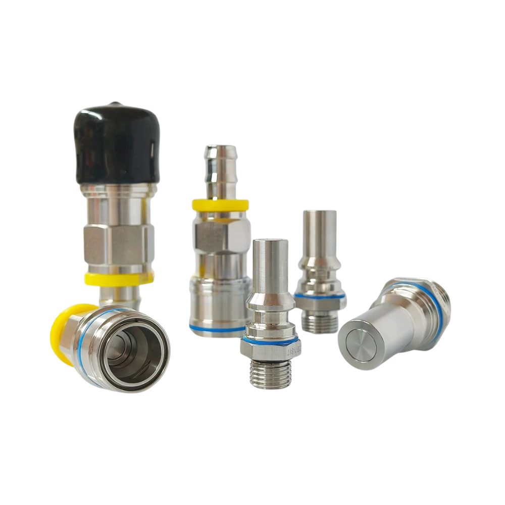
RENHOTEC supplies OCP UQD and UQDB couplings for the rack-level liquid cooling interface, in the four standard sizes and with blind-mate options. We do not supply the in-tray fittings and coolant interconnects. Send us your tray count, your supply-and-return arrangement, and whether the tray blind-mates, and we will work through the rack-level quantity and specification with you.
The interface descriptions and figures above come from the following primary documentation. Where an OEM implementation differs, its own documentation takes precedence.