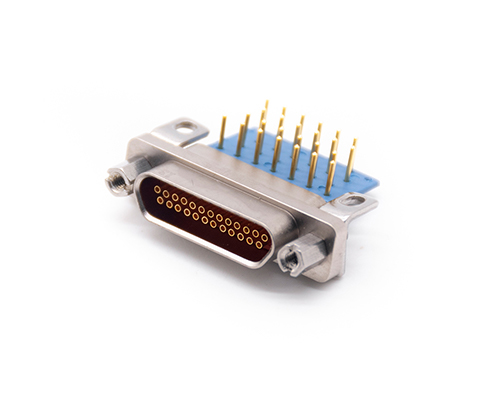
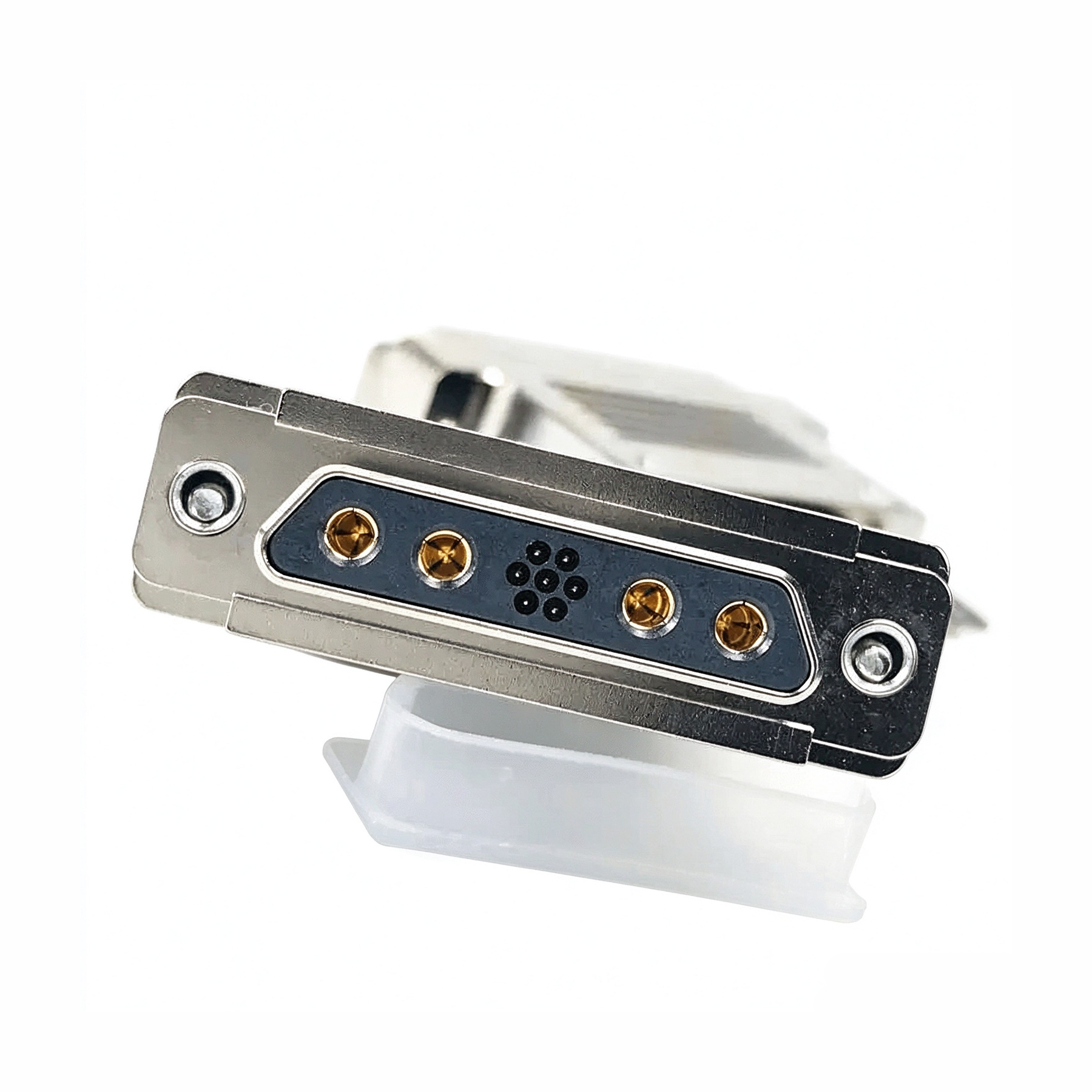
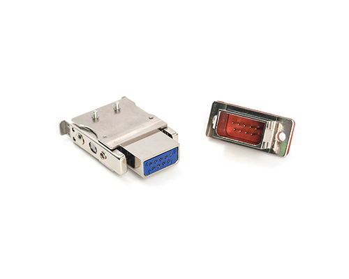
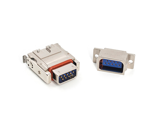
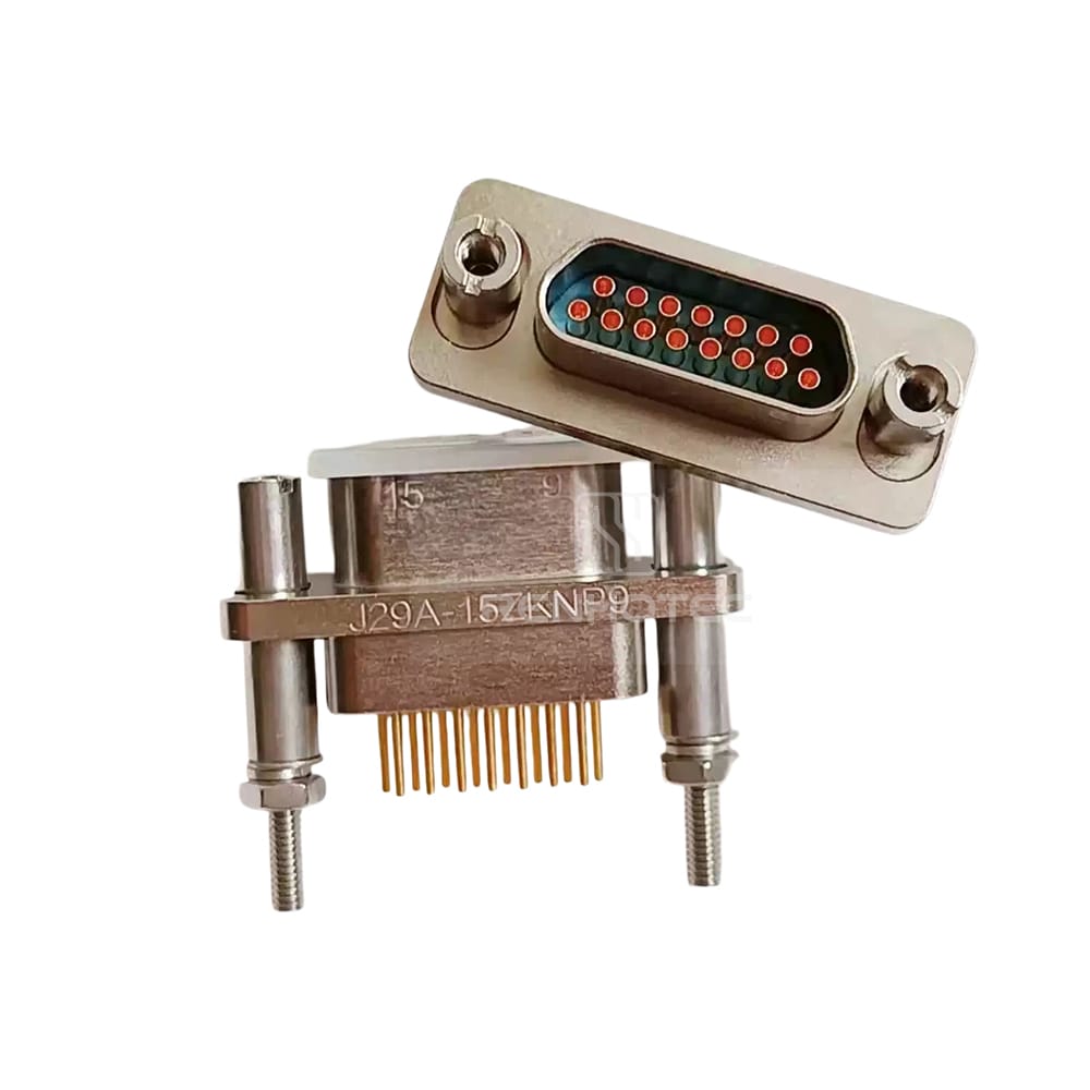
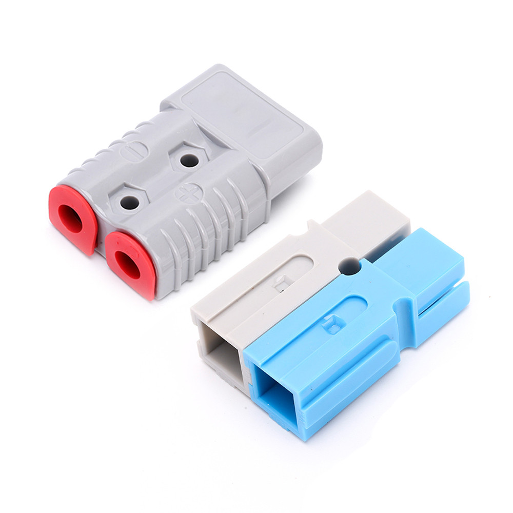
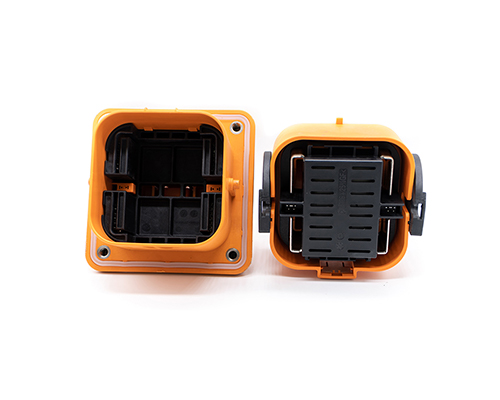
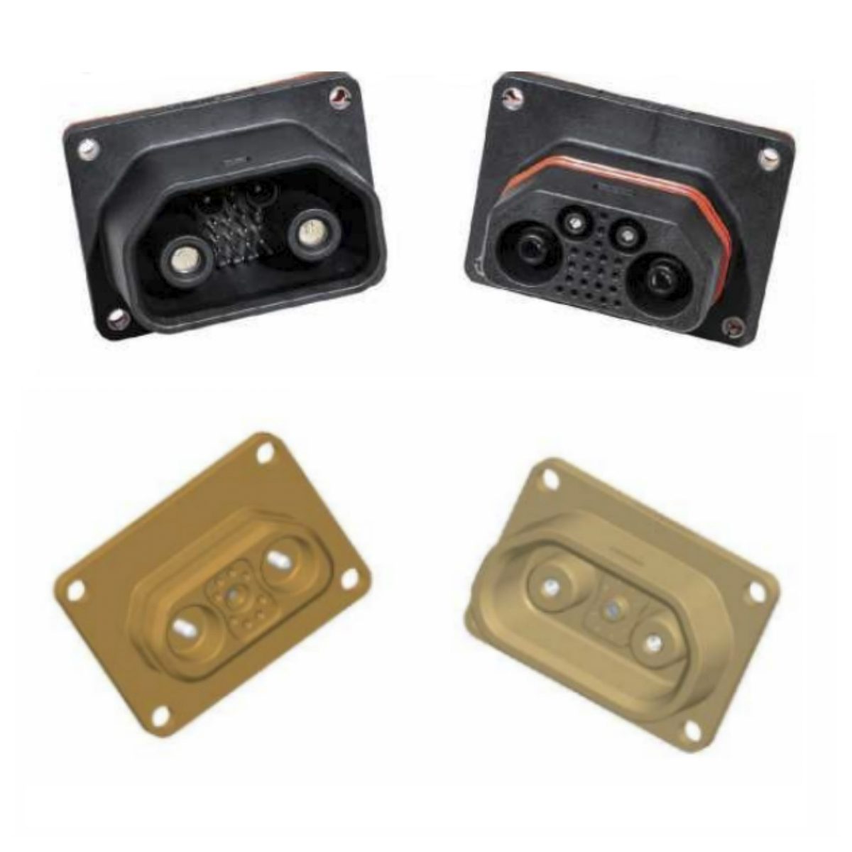
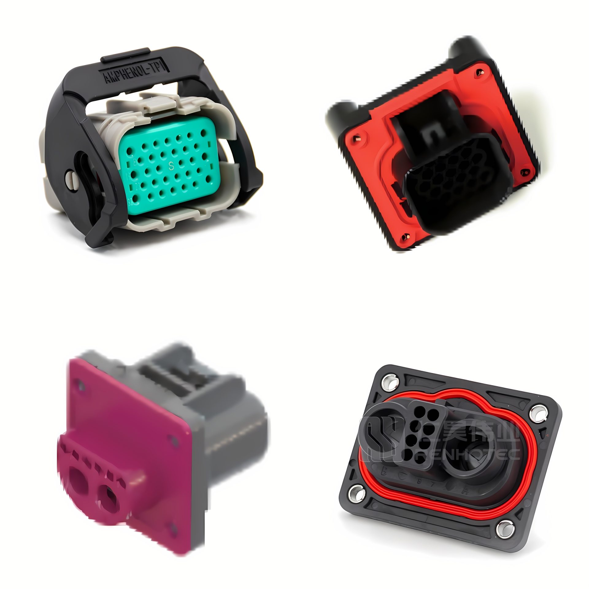
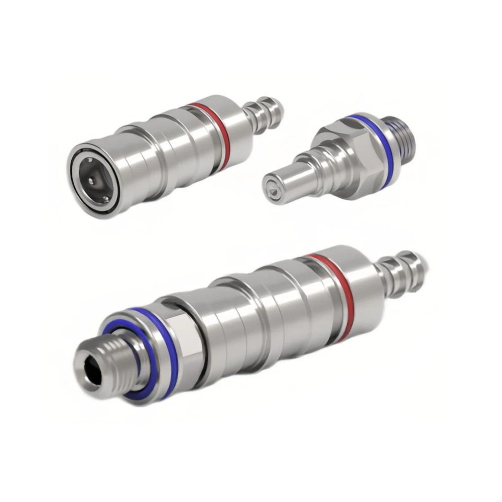
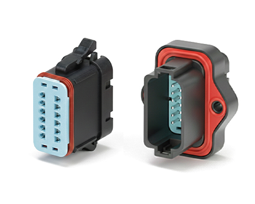
The Rectangular Connector is widely used in aerospace, medical instruments, consumer electronics (such as computers, TVs, game consoles, etc.), industrial control equipment, communication equipment, and automotive electronics. With its reliable connection performance, diverse specifications, and relatively convenient plug-in and unplug operations, it has become an indispensable component in various electronic and electrical applications.
J30J General Connectors and Cable Assemblies
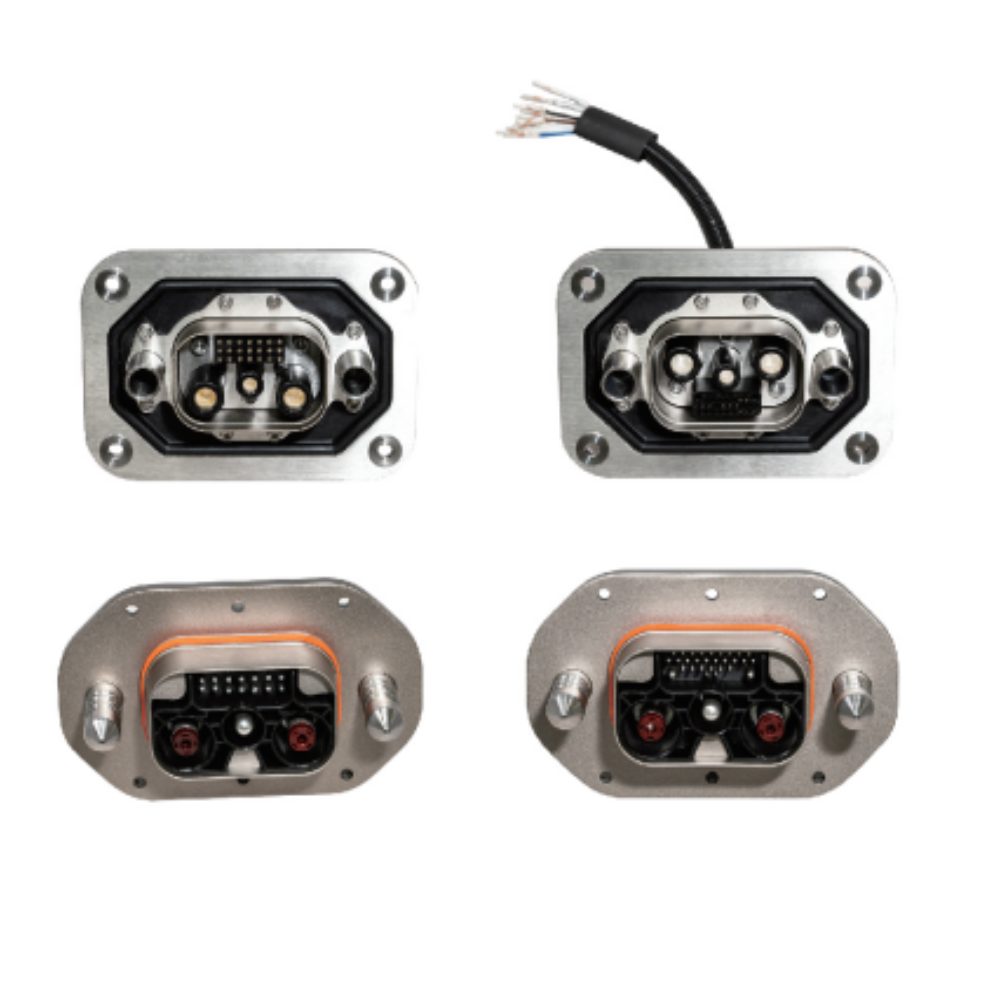
J30J Mixed Current (Hybrid) Connectors and Cable Assemblies
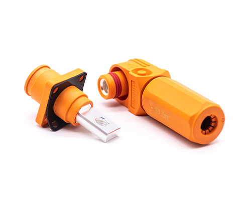
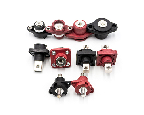
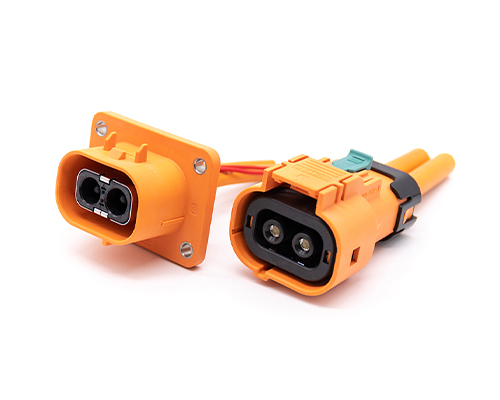
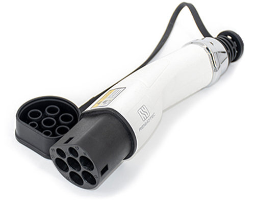
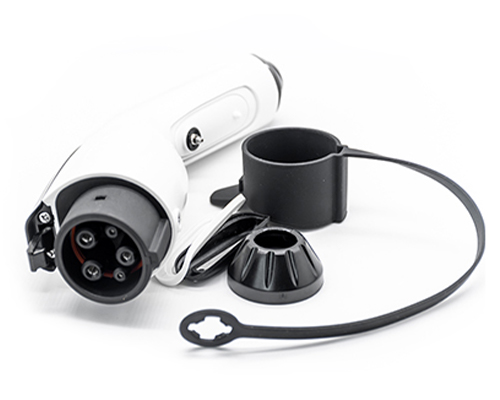
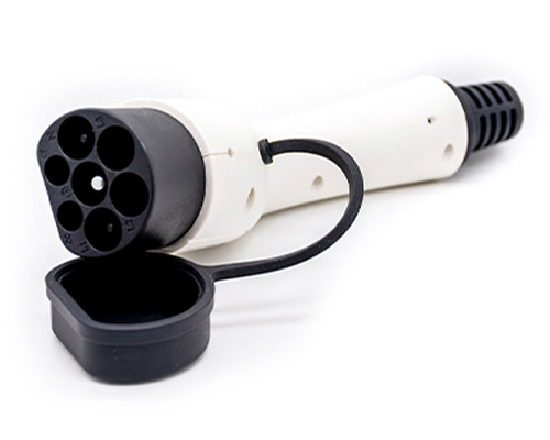
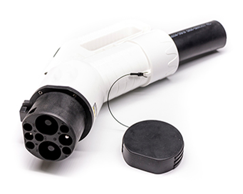
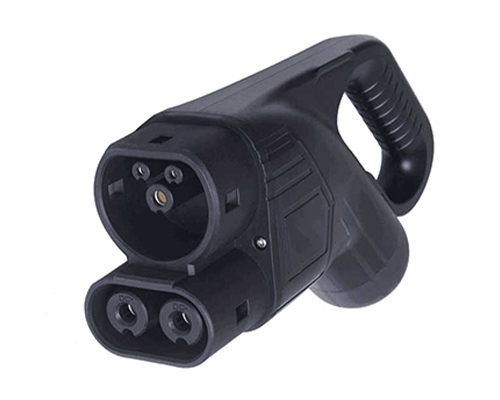
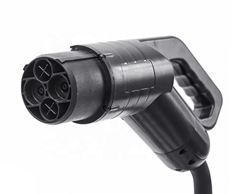
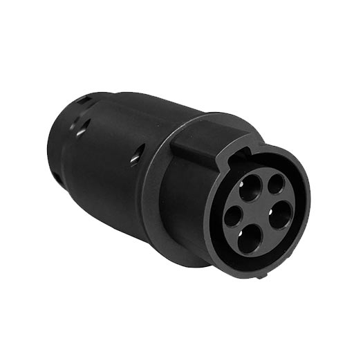
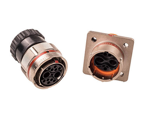
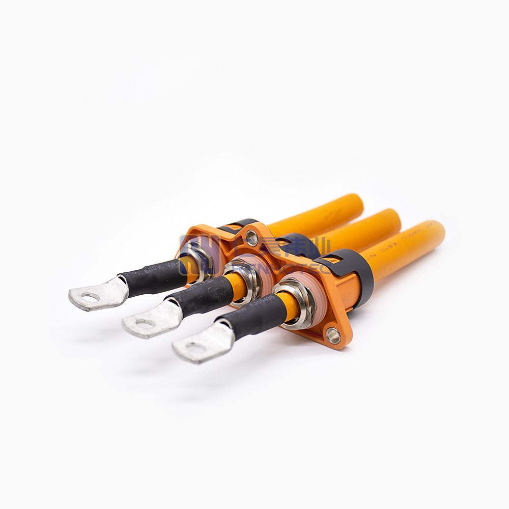
High Voltage Connectors are widely used in EV power systems, renewable energy installations, and industrial high-voltage circuits. Renhotec’s series drives the building of efficient, safe, and sustainable electrical ecosystems, meeting current technological demands.
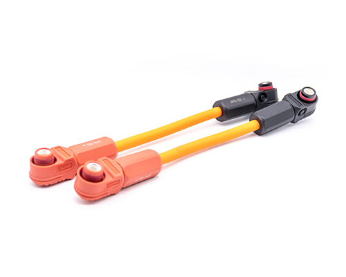
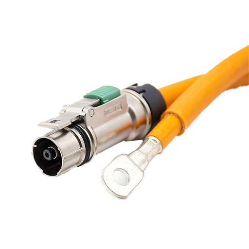
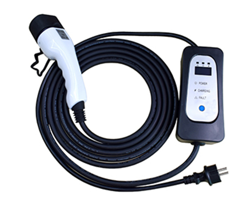
Renhotec EV Cable, crafted with top-notch conductive materials and meticulously engineered insulation, showcases outstanding impedance control and voltage-withstanding properties. Its design combines flexibility and durability to meet a wide array of installation needs. This cable is widely utilized in grid interconnections, large-scale industrial power supply systems, and high-voltage renewable energy projects, enabling smooth and efficient power transmission.
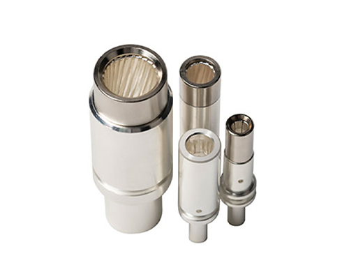
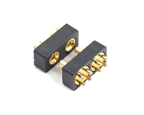
Renhotec, as a professional supplier, offers a comprehensive range of these Signal Transmission Connector products. Whether it is the high-reliability applications of the metal series or the wide adaptability of the plastic series in consumer electronic products, Renhotec can provide customers with high-quality options to meet the diverse requirements of signal transmission connections in different industries and scenarios.
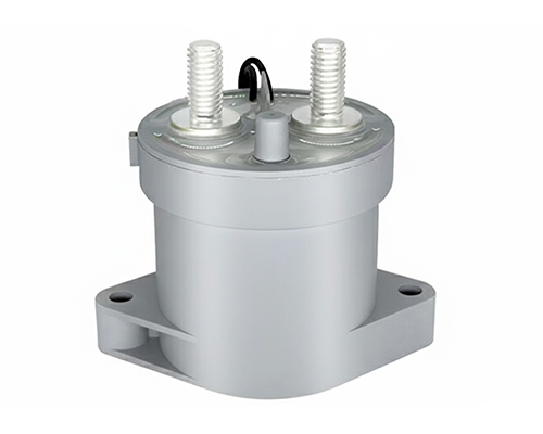
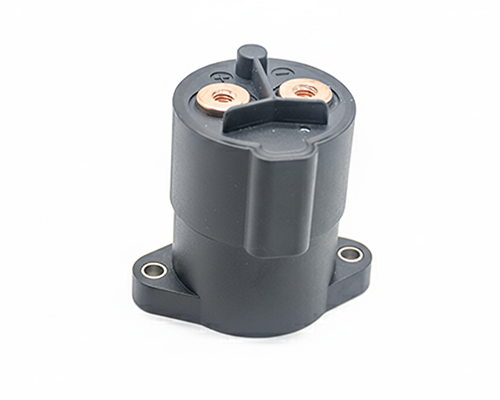
Renhotec, active in electrical components, offers High Voltage DC Contactors in Epoxy Resin Sealing and Ceramic Sealing variants, with a 20A – 1000A current range. The Epoxy Resin Sealing one is cost-effective and protective. The Ceramic Sealing variant excels in thermal stability and insulation. They’re widely used in EV charging, renewable energy grid, and industrial high-voltage DC power distribution for reliable circuit control and current interruption, providing comprehensive solutions for multiple sectors.
A J30J combo Micro-D connector — also called a mixed-current J30J, hybrid J30J, or hybrid Micro-D connector — is a single rectangular connector that carries two kinds of contacts in the same metal shell:
3A signal contacts for data, control, or low-power lines.
20A power contacts for supply lines, motors, heaters, or other higher-current loads.
In other words, you get a power + signal Micro-D in one package. Instead of running one small connector for signals and a second larger connector for power, you can use one J30J mixed-current connector. That saves space, cuts the bill of materials, and simplifies assembly.
The J30J combo series follows the same family outline as the standard J30J Micro-D (a Chinese equivalent to the MIL-DTL-83513 / MDM family), but the contact layout is completely separate. You cannot mate a J30J combo connector with a standard J30J connector. They look similar from the outside, but the contact patterns inside are different.
Wire sizes are also split: small-current contacts take 0.10–0.15 mm² wire, while large-current contacts take 2.0–3.0 mm² wire.
2. Why Choose a J30J Mixed-Current Connector?
If your system needs both signal and power lines in a tight space, a combo Micro-D connector is often the cleanest answer. Here is why engineers and buyers look at the J30J mixed-current series:
One connector instead of two Fitting two separate connectors means twice the mounting holes, twice the wire routing, and twice the assembly labor. Combining them into one metal shell removes that duplication.
20A power density Most standard Micro-D connectors only carry about 3A per contact. The J30J combo version adds dedicated 20A power contacts in the same shell size. That is a big jump for equipment where space is limited but current demand is real.
Built for harsh conditions The standard shell works from -55°C to +125°C, resists vibration up to 196 m/s², and handles 735 m/s² shock. A marine-resistant M1 stainless-steel shell is also available for salt-spray environments.
3. J30J Combo Micro-D vs. Standard J30J
Do not mix these two up. They share the same family name, but they are not interchangeable.
Feature
Standard J30J
J30J Combo / Mixed Current
Contact type
One size only: 3A signal contacts
3A signal contacts plus 20A power contacts
Layout codes
9, 15, 21, 25, 31, 37, 51, 66, 74
02P02 to 10P10 and mixed codes like 09P02, 21P02, 39P02
Part-number system
TJ / ZK based
10-section code with separate signal and power fields
Can mate together?
No
No
Best use case
Pure signal/control boards
Boards that need power and signal in one connector
If you are replacing or cross-referencing an existing J30J connector, check the contact layout code first. The combo series has its own numbering system, which we explain in the next section.
There are 18 standard arrangements in the catalog:
5. How to Read the J30J Part Number
A J30J combo Micro-D part number has up to 10 fields. Here is what each one means, using J30J 27P02 J S 000 S0 000 0 as an example.
J30J
1
—
27P02
2
—
J
3
—
S
4
—
000
5
—
S0
6
—
000
7
—
0
8
No.
Code
Description
Options
1
J30J
Series / Basic Type
Micro-D Rectangular Connector, Mixed High-Low Current Layout
2
27P02
Contact Arrangement
20A Only
02P02 — 2 × 20A
03P03 — 3 × 20A
04P04 — 4 × 20A
05P05 — 5 × 20A
06P06 — 6 × 20A
07P07 — 7 × 20A
08P08 — 8 × 20A
09P09 — 9 × 20A
10P10 — 10 × 20A
Mixed 3A + 20A
09P02 — 7 × 3A + 2 × 20A
11P04 — 7 × 3A + 4 × 20A
12P05 — 7 × 3A + 5 × 20A
13P06 — 7 × 3A + 6 × 20A
16P03 — 13 × 3A + 3 × 20A
21P02 — 19 × 3A + 2 × 20A
23P06 — 17 × 3A + 6 × 20A
25P02 — 23 × 3A + 2 × 20A
27P04 — 25 × 3A + 2 × 20A
39P02 — 37 × 3A + 2 × 20A
3
J
Low-Current Contact Type
0 — None
J — Pin
K — Socket
4
S
High-Current Contact Type
S — Socket (Plug)
P — Pin (Receptacle)
Segments 3 and 4 accept only these combinations: 0S, 0P, JS, KP.
5
000
Low-Current Termination Style
000 — None
C00 — Crimp
S00 — Solder
N0x — Straight PCB
W0x — Right Angle PCB
6
S0
High-Current Termination Style
C0 — Crimp
S0 — Solder
Nx — Straight PCB
Wx — Right Angle PCB
Should match Segment 5; solder and crimp can be mixed on request (e.g., S00C0, C00S0).
7
000
Locking Hardware Type
000 — None
L00 — Free-end Locking Assembly
K00 — Free-end Locking Assembly, Hand-tightenable
P — Fixed-end Locking Assembly
Fixed-end assemblies come in multiple codes (P00–P54) covering different mounting methods and panel thicknesses.
8
0
Shell Type
0 — Standard, Nickel-plated Aluminum Alloy
1 — Stainless Steel
M1 — Marine-grade Stainless Steel
A few things to remember:
In the combo series, P means a 20A pin and S means a 20A socket. This is different from the standard J30J, where P and S often describe mounting style.
The small-current and large-current sides can only combine as 0S, 0P, JS, or KP.
A plug normally uses JS (small pins + large sockets). A socket normally uses KP (small sockets + large pins).
The two termination fields are usually the same, but mixed crimp/solder combinations can be requested for special builds.
6. Key Specifications
Parameter
Value
Rated current
3A per signal contact; 20A per power contact
Contact resistance
≤ 10 mΩ
Insulation resistance
≥ 5,000 MΩ at room temperature; ≥ 100 MΩ under damp heat
Dielectric strength
800 V at sea level
Operating temperature
-55°C to +125°C
Relative humidity
Up to 98% at +40°C
Vibration
10–2000 Hz, 20G
Random vibration
0.4 G²/Hz PSD, 23.1 G RMS total
Shock
75G
Mechanical life
500 cycles
Salt spray
48 h (standard); marine-resistant M1 shell available
7. Termination Styles and Dimensions
The J30J combo series supports four termination styles for each contact size:
Crimp and solder are the most common choices for cable assemblies. PCB versions are used when the connector mounts directly to a printed circuit board.
Overall size range (L × W × H, mm)
E.g., A Soldering J30J Combo Micro-D Connector Dimensional Drawing
The family covers a wide range. For reference, the smallest layout (02P02) is about 23 × 19 × 13 mm, while the largest standard layout (10P10 / 09P09) is about 56 × 52 × 46 mm. Exact dimensions depend on the arrangement, shell, and locking hardware.
8. Shell Materials and the Marine-Resistant Option
The shell code is simple:
0 — Standard aluminum shell with nickel plating. This is the default for most applications.
I — Stainless steel. Use this when you need better corrosion resistance or a stronger shell.
M1 — Marine-resistant stainless steel. Built for salt spray, acidic atmosphere, and fungus exposure. Choose this for ships, coastal equipment, or other harsh outdoor environments.
For indoor industrial or laboratory use, the standard aluminum shell is usually enough. Move up to I or M1 only when the environment demands it.
9. Accessories: Tail Clamps and Locking Hardware
A complete J30J combo connector is usually made of the main insert plus separate hardware. Do not forget these parts when you order.
Tail clamp A3 The A3 is a two-piece cable clamp. It is only used with crimp or solder terminations. It helps strain-relieve the cable bundle as it exits the connector. If you choose a PCB-mount version, you normally do not need it.
Locking hardware
000 — No locking hardware.
L00 / K00 — Free-end locking hardware. K00 can be operated by hand without tools.
P00–P13 — Fixed-end locking hardware for panel or PCB mounting. The code depends on whether it mounts from the front or rear of the panel and on the panel thickness.
Important: A fully usable connector is usually the contact insert + locking hardware. For cable builds, add the A3 tail clamp if needed. Missing the locking hardware is a common ordering mistake.
10. Typical Applications
The J30J combo Micro-D fits anywhere a small enclosure needs both power and control lines. Common uses include:
Avionics electronics
Communication and test systems
Industrial control cabinets
Measurement and data-acquisition equipment
Robotics and motor drives
If your checklist includes “limited space” and “needs power plus signal,” the J30J mixed-current series is a strong candidate.
11. How to Select a J30J Combo Micro-D Connector
Follow these six steps to build a valid part number:
Count your channels. How many 3A signal lines and 20A power lines do you need?
Pick the arrangement code. Use the [total] P [20A] format. For example, 5 power-only contacts = 05P05; 25 signals + 2 power = 27P02.
Choose the contact gender. Plug side = small pin + large socket (JS or 0S). Socket side = small socket + large pin (KP or 0P).
Choose the termination style. Crimp, solder, straight PCB, or right-angle PCB.
Choose the locking hardware. Free-end (L00/K00) or fixed-end (P00–P13) based on your panel or board mounting.
Choose the shell and accessories. Standard aluminum (0), stainless steel (I), or marine-resistant (M1). Add A3 tail clamp for crimp/solder cable builds.
If you are unsure about steps 3–6, send us the first two items — signal count and power count — and our engineers can match the rest.
J63A — A 0.635 mm ultra-miniature Micro-D for very tight spaces.
If you see a J30J-style model number that does not match the standard or combo layout, it probably belongs to one of these branches.
13. Frequently Asked Questions
What is a J30J combo Micro-D connector? It is a Micro-D connector that mixes 3A signal contacts and 20A power contacts in one metal shell. It is also called a mixed-current J30J or hybrid Micro-D.
Is “combo Micro-D” the same as “hybrid Micro-D”? Yes. Both terms describe a Micro-D connector with power and signal contacts in the same shell.
Can a J30J combo connector mate with a standard J30J? No. The contact arrangements are completely different, even though the shells look similar.
What is the largest signal-count arrangement? 39P02 gives you 37 signal contacts and 2 power contacts, for a total of 39 positions.
Should I choose crimp or solder? Crimp is better for production because it is faster and more repeatable. Solder is convenient for prototypes, repairs, and small runs.
Do I need to order locking hardware separately? Yes. The part number includes a locking-hardware field for a reason. The contact insert alone is not a finished connector.
Can you supply custom cable assemblies? Yes. We can build complete cable harnesses based on your drawing or sample.
What is the typical MOQ and lead time? MOQ and lead time depend on the exact part number and quantity. Send the part number or your requirement for a fast quote.
14. Why Choose Renhotec for J30J Combo Micro-D Connectors
We keep both the standard J30J and the J30J combo / mixed-current lines in our catalog. That makes cross-referencing and second-sourcing easier.
If you are currently buying combo Micro-D or MDM-style connectors, our J30J mixed-current series offers a compatible mechanical and electrical class with shorter lead times and better unit economics.
Our engineering team can help you:
Match an existing part number to the correct J30J combo layout.
Build a complete bill of materials, including locking hardware and A3 tail clamps.
Design custom cable assemblies with the right wire sizes and lengths.
Provide samples for prototype builds before you commit to volume.
You do not need to be a connector expert to order. Send us your signal count, power count, and application, and we will guide you through the rest.
15. How to Send an Inquiry
You don’t need a complete part number before you contact us. If you have one, just send it and we will quote it directly. If you don’t, simply tell us how many signal lines and how many power lines you need, together with your quantity and your target date — our engineers will help you work out the rest of the specification from there.
We also build custom cable assemblies, so a drawing or a sample photo is always welcome. If you are comparing us against an existing imported part, mention the model you are using now, and we will tell you whether the J30J combo series is a direct match.
Email [email protected] or click here to fill in the inquiry form. We normally reply within one business day.
Let us know how we can help?
We look forward to hearing from you! We will respond within 24 hours.