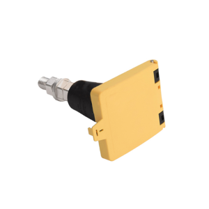
Choosing the wrong UQD connector size for your liquid cooling loop is expensive. An undersized coupling chokes flow and forces your pump to work harder. An oversized one wastes space, costs more, and can increase connection force beyond what your hardware tolerates.
This guide maps each UQD size to real data center cooling scenarios. Whether you are sizing a single GPU cold plate or a rack-level manifold, you will find the right spec in under two minutes.
What Is a UQD Connector?
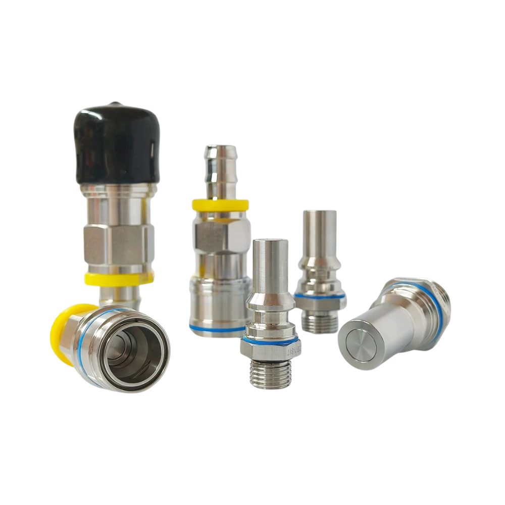
UQD stands for Universal Quick Disconnect. It is an open-standard liquid cooling quick connector specification maintained by the Open Compute Project (OCP). A conforming UQD pair is designed to be:
- Vendor-interchangeable — plugs and sockets from different brands mate correctly within the same size
- Drip-free — double shut-off valves limit fluid loss during disconnection
- Hot-pluggable — single-handed push-to-connect operation for server maintenance
UQD covers single-phase water and glycol cooling loops for electronic equipment. It is not intended for combustible fluids, high-temperature oil, or hydraulic systems.
Quick note on UQDB: UQDB is the blind-mate variant of UQD. It connects automatically as a server slides into its rack slot, without direct hand access. We cover when to choose UQDB over UQD later in this guide.
UQD Size Overview — At a Glance
OCP defines four nominal interface sizes. The size code describes the standardized mating interface, not the hose outside diameter.
| Size |
Nominal Interface |
Min Cv |
Recommended Flow |
Max Fluid Loss |
Typical Use |
| UQD02 |
1/8 in (3.2 mm) |
0.25 |
0.6 GPM (2.3 L/min) |
0.020 mL |
Small internal connections, low-power cold plates |
| UQD04 |
1/4 in (6.4 mm) |
0.80 |
1.7 GPM (6.4 L/min) |
0.025 mL |
Single GPU/CPU cold plates |
| UQD06 |
3/8 in (9.5 mm) |
1.60 |
3.0 GPM (11.4 L/min) |
0.035 mL |
Multi-GPU series, server-level connections |
| UQD08 |
1/2 in (12.7 mm) |
2.40 |
4.7 GPM (17.8 L/min) |
0.070 mL |
Rack manifold mainlines, CDU connections |
Key rule: Select a size with a Cv value at least 30% higher than your calculated requirement. This margin absorbs pressure pulsations, flow fluctuations, and long-term seal wear.
What is Cv? The flow coefficient (Cv) measures how many gallons of water pass through per minute at a 1 psi pressure drop. A higher Cv means lower flow restriction.
How to Select the Right Size
Follow these three steps in order.
Step 1: Calculate Required Flow Rate
Use the heat removal equation:
Q = P / (C × ΔT × ρ)
Where:
- Q = required flow rate (L/min)
- P = cooling power (W) × liquid cooling ratio (typically 0.75–0.85)
- C = specific heat capacity — water ≈ 4.18 kJ/kg·K, PG25 ≈ 3.8 kJ/kg·K
- ΔT = supply/return temperature difference (K), typically 8–15 K
- ρ = coolant density (kg/L) — water ≈ 1.0, PG25 ≈ 1.03
Example: A single GPU cold plate with 700 W thermal load, 80% liquid cooling ratio, 10 K ΔT, using water:
Q = (700 × 0.8) / (4.18 × 10 × 1.0) ≈ 13.4 L/min
Step 2: Match to UQD Size
Apply the 30% margin to your calculated Q, then match:
| Calculated Flow (with 30% margin) |
Recommended Size |
| < 3 L/min | UQD02 |
| 3–8 L/min | UQD04 |
| 8–15 L/min | UQD06 |
| ≥ 15 L/min | UQD08 |
From the example above: 13.4 L/min × 1.3 = 17.4 L/min → UQD06 is the minimum; UQD08 gives more headroom.
Step 3: Verify Pressure Drop Budget
Every UQD in your loop adds pressure drop. Sum the drops across all couplings, hoses, cold plates, and manifolds. The total must stay within your pump’s head capacity.
If your pump has limited head margin, prefer the next larger UQD size or reduce the number of couplings in series.
UQD vs UQDB: Manual or Blind-Mate?
Not every liquid cooling connection should use the same architecture. The choice depends on how your hardware is accessed.
| UQD vs UQDB Decision Flow |
| Step / Question |
Condition |
Recommendation |
| Step 1: Is the coupling directly accessible by hand? |
Yes → accessible |
Go to Step 2 |
| No → not accessible |
Go to Step 3 |
| Step 2: Maintenance frequency > 500/year? |
Yes |
Use UQDB
High-durability blind-mate |
| No |
Use UQD
Standard manual push-to-connect |
| Step 3: Rack density > 40 kW or 40+ nodes? |
Yes |
Use UQDB
Auto-align for dense racks |
| No |
Re-evaluate
UQD may still work |
| Factor |
UQD (Manual) |
UQDB (Blind-Mate) |
| Connection method | Hand-aligned, push-to-connect | Auto-aligns as server slides into rack |
| Access requirement | Direct hand access to coupling | No direct access needed |
| Alignment tolerance | Precise (±0.5 mm) | Radial tolerance ±1 mm |
| Typical application | CDU, manifold, serviceable cold plates | High-density AI racks, hot-swap nodes |
| Cost | Lower | Higher (guides + floating mechanisms) |
| Mating cycles | 5,000+ | 5,000+ |
Choose UQD when:
- The connection is designed for periodic human maintenance
- The rack density is moderate and operators can reach every coupling
- Cost is a primary constraint
Choose UQDB when:
- The server or module must slide in and out without plumbing rework
- Rack density exceeds ~40 kW or 40+ nodes per rack
- Maintenance frequency is high and tool-less swaps are required
Can you mix UQD and UQDB in the same loop? Yes, at different points. Use UQDB at the server-to-manifold interface and UQD at the manifold-to-CDU connection where operators have access.
Connection Type: UNF, BSP, or Hose Barb?
After selecting the size and architecture, choose how the connector terminates into your equipment.
| Connection |
Standard |
Best For |
Watch Out |
| UNF (O-ring boss) |
SAE J1926 / OCP default |
OEM equipment, North American hardware |
Verify ORB size (-04, -06, -08, -10) |
| BSP (G-thread) |
ISO 1179 |
European/Asian equipment, field retrofits |
BSPP is parallel; use bonded washer or face seal |
| Hose barb |
— |
Flexible hose assemblies, custom routing |
Use clamp retention; verify hose ID compatibility |
Quick mapping:
- OEM server or CDU with machined ports → UNF ORB
- Existing facility plumbing with BSP fittings → BSP to match
- Custom hose assemblies or prototype builds → Hose barb
UQD02 note: Minimum socket termination is 1/4 in EPDM hose barb; minimum plug termination is -04 ORB. The hose barb is larger than the nominal interface — this is normal and specified by OCP.
Common Sizing Mistakes to Avoid
| Mistake |
Consequence |
Correct Approach |
| Selecting for bare minimum flow | Insufficient cooling, pump overload | Size for 1.3× calculated flow |
| Ignoring pressure drop accumulation | Pump head exceeded, flow collapses | Sum all component drops in the loop |
| Mixing UQD and UQDB at the same interface | Mechanical mismatch, leakage | Match architecture to access pattern |
| Wrong connection type for the port | Leaks, stripped threads, field rework | Verify port standard before ordering |
| Overlooking coolant compatibility | Seal swell, degradation, leaks | Confirm seal material (EPDM/FKM) matches your coolant |
Quick Selection by Application
Skip the math. If you know your application, start here:
| Application |
Typical Power |
Recommended Size |
Notes |
| Single GPU cold plate (e.g., H100) |
300–700 W |
UQD04 |
Use UQD06 for 700 W+ with small ΔT |
| 4-GPU server (series manifold) |
1,200–2,800 W |
UQD06 |
Or 2× UQD04 in parallel for lower pressure drop |
| Rack manifold (supply/return) |
30–100 kW per rack |
UQD08 |
Use multiple in parallel for >100 kW |
| CDU to facility loop |
100+ kW |
UQD08 |
Match to facility hose size (typically 1/2 in or larger) |
| Low-power auxiliary cooling |
< 200 W |
UQD02 |
Internal connections only, not for main cooling loops |
Tip: Always size for 1.3× calculated flow. When in doubt between two sizes, choose the larger one.
RENHOTEC UQD & UQDB Series
RENHOTEC manufactures UQD and UQDB connectors across all four OCP sizes. The product line covers:
- UQD manual connectors — plug and socket configurations with UNF, BSP, and hose barb terminations
- UQDB blind-mate connectors — auto-aligning pairs for high-density server racks
- Full material documentation — SS316L bodies, EPDM standard seals, optional FKM for aggressive coolants
- OCP specification compliance — dimensional and performance testing against OCP UQD v1.0
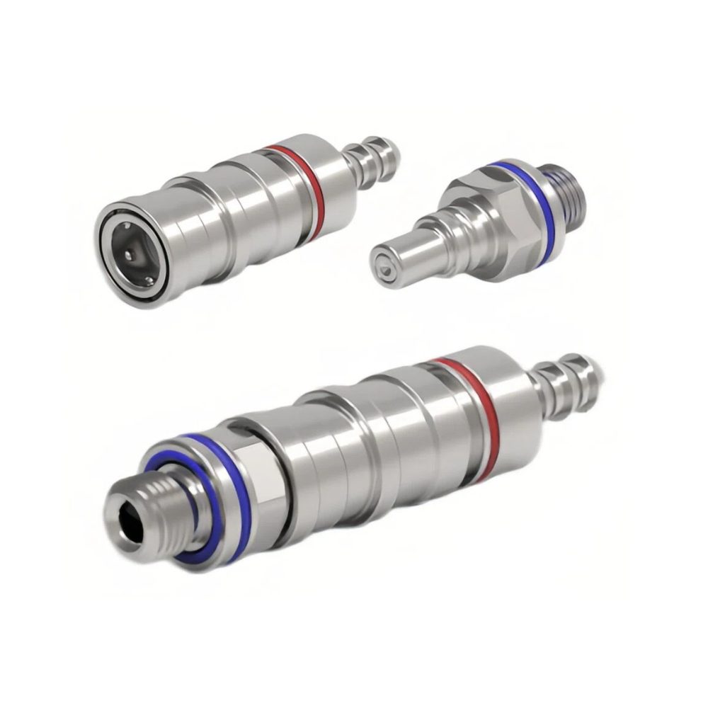
All sizes are available with color-coded rings (red/blue) for supply/return identification.
Browse the RENHOTEC UQD & UQDB Series for full model listings, dimensional drawings, and termination options.
Need Help Sizing Your Loop?
If you are unsure which UQD size fits your cooling architecture, our engineers can review your thermal budget and loop layout.