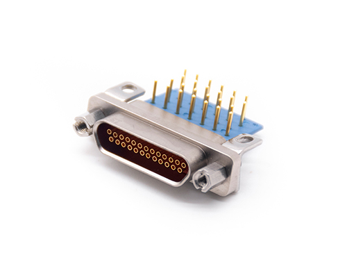
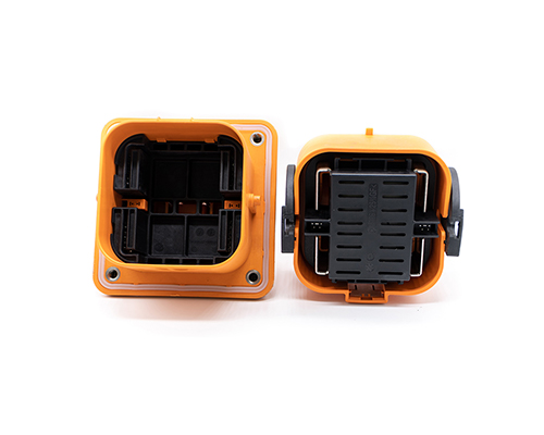
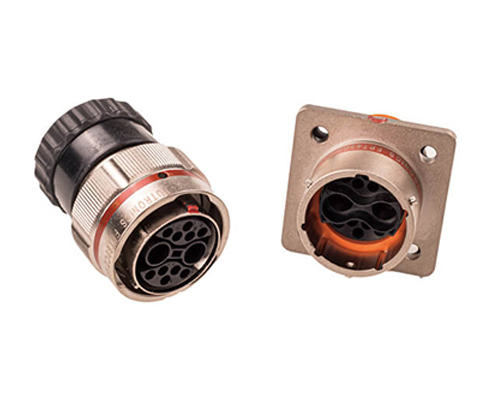
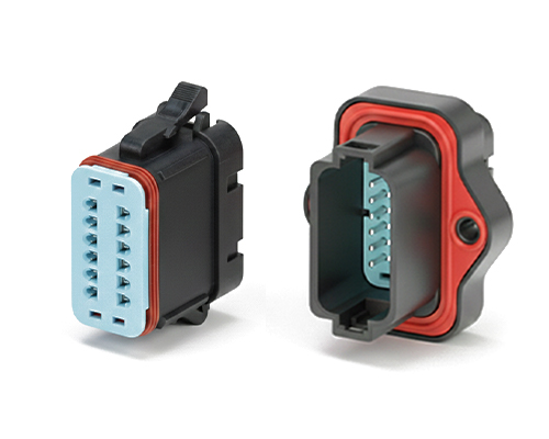
The Rectangular Connector is widely used in aerospace, medical instruments, consumer electronics (such as computers, TVs, game consoles, etc.), industrial control equipment, communication equipment, and automotive electronics. With its reliable connection performance, diverse specifications, and relatively convenient plug-in and unplug operations, it has become an indispensable component in various electronic and electrical applications.
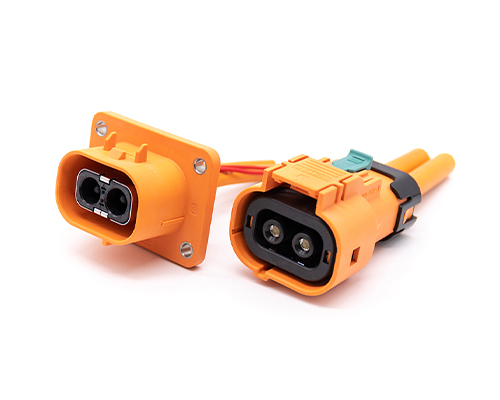
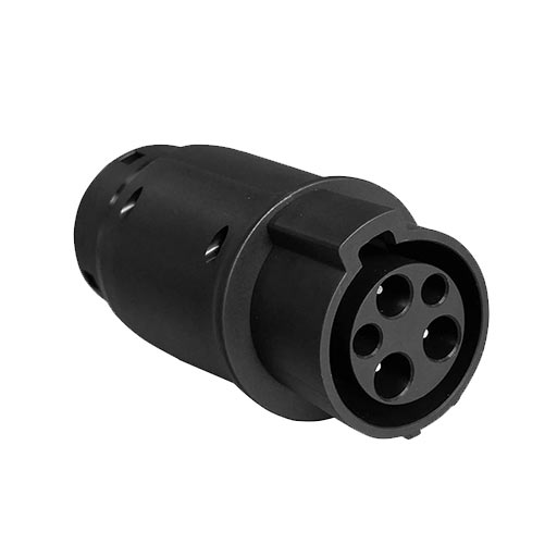
High Voltage Connectors are widely used in EV power systems, renewable energy installations, and industrial high-voltage circuits. Renhotec’s series drives the building of efficient, safe, and sustainable electrical ecosystems, meeting current technological demands.
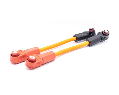
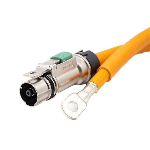
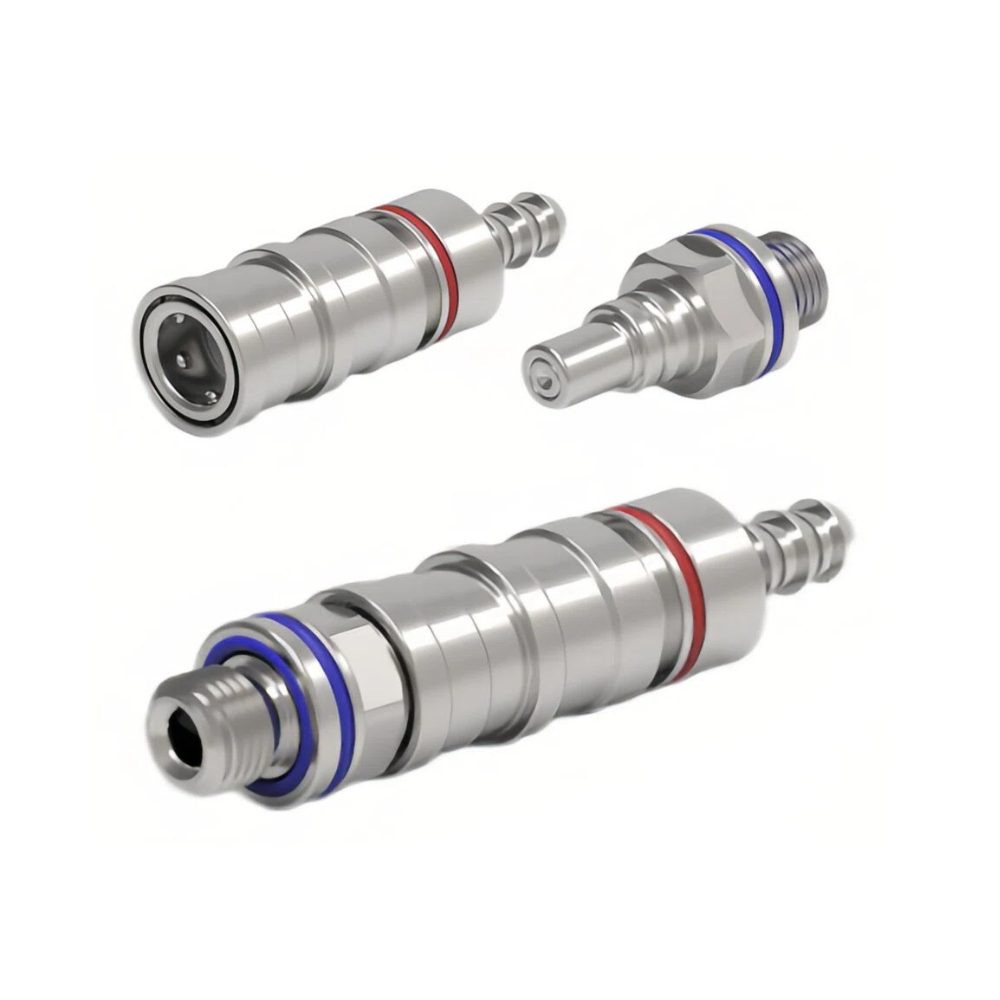
Renhotec EV Cable, crafted with top-notch conductive materials and meticulously engineered insulation, showcases outstanding impedance control and voltage-withstanding properties. Its design combines flexibility and durability to meet a wide array of installation needs. This cable is widely utilized in grid interconnections, large-scale industrial power supply systems, and high-voltage renewable energy projects, enabling smooth and efficient power transmission.
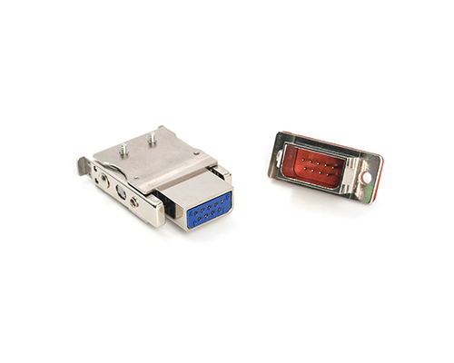
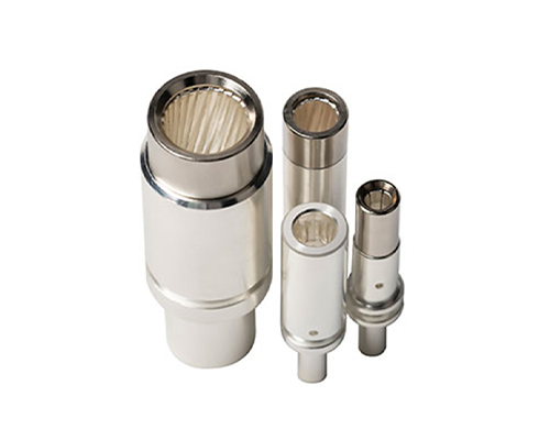
Renhotec, as a professional supplier, offers a comprehensive range of these Signal Transmission Connector products. Whether it is the high-reliability applications of the metal series or the wide adaptability of the plastic series in consumer electronic products, Renhotec can provide customers with high-quality options to meet the diverse requirements of signal transmission connections in different industries and scenarios.
Renhotec, active in electrical components, offers High Voltage DC Contactors in Epoxy Resin Sealing and Ceramic Sealing variants, with a 20A – 1000A current range. The Epoxy Resin Sealing one is cost-effective and protective. The Ceramic Sealing variant excels in thermal stability and insulation. They’re widely used in EV charging, renewable energy grid, and industrial high-voltage DC power distribution for reliable circuit control and current interruption, providing comprehensive solutions for multiple sectors.
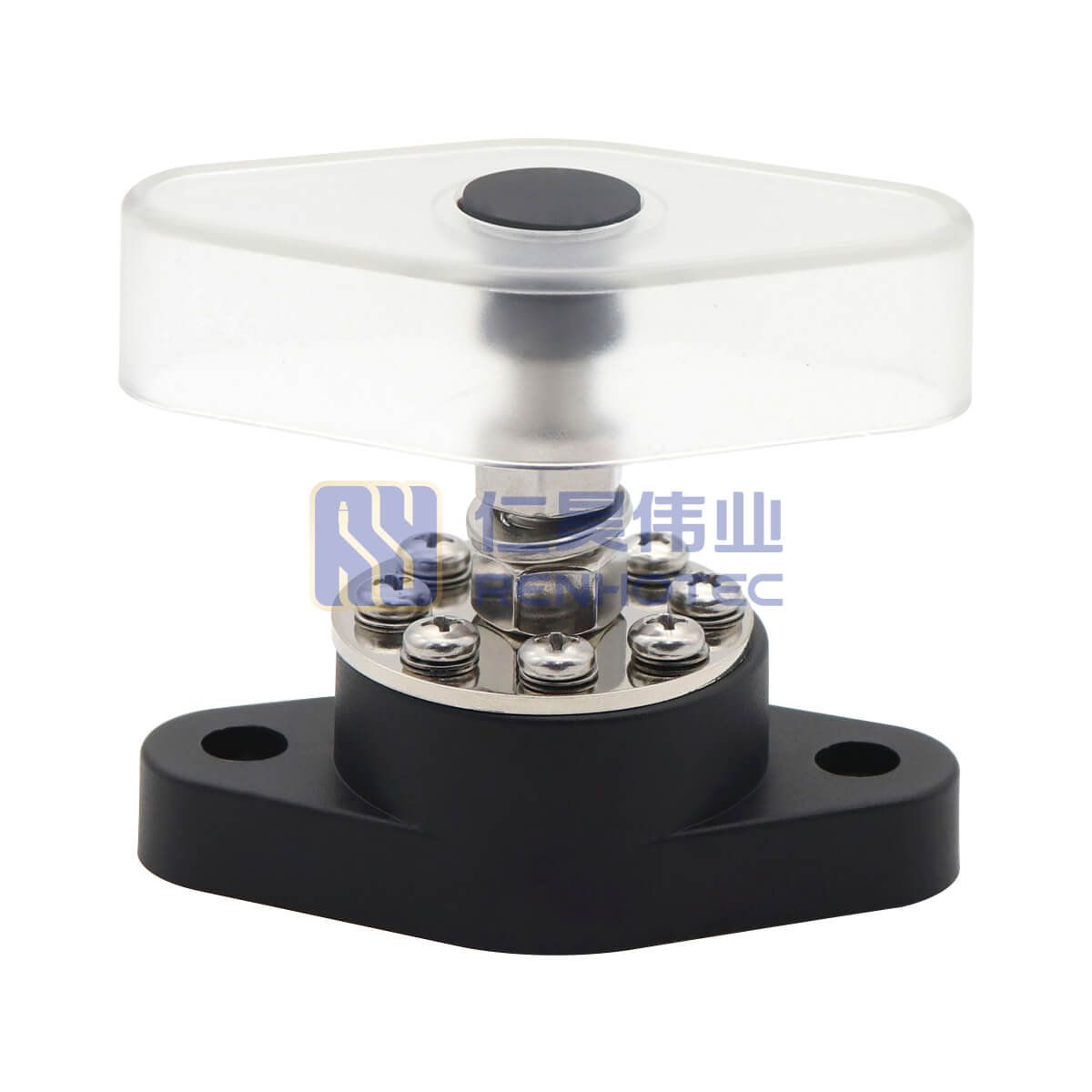
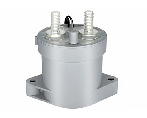
Global industry is now fully transitioning to electrification. In particular, the rapid development of 800V electric vehicle platforms and large-scale marine energy storage systems has raised the performance requirements for electrical connection components to unprecedented levels. In these systems, high-current terminal studs are critical junctions where electrical efficiency meets structural integrity. Selecting a terminal that does not align with system requirements can lead to localized overheating or parasitic heat. To improve system security and lifespan, we need to pay attention to the following aspects.
1. Strategic Rating: Redundancy and Assembly Validation
In many product catalogs, you will see terminals rated at 120A, 150A, or 200A. However, professional engineers must view these as baseline ratings determined under controlled laboratory conditions.
The 150% Redundancy Strategy: For professional B2B applications, the 150% rule is a recommended starting point. If your system draws a continuous 100A, specifying a terminal rated for 150A helps account for peak surges and prevents the component from operating at its thermal limit.
Thermal Derating & Validation: Redundancy is a starting point; actual temperature rise (dT) must be validated in the final assembly. If a terminal is placed inside a cramped, unventilated battery box, its effective capacity drops. Always consult a derating curve to ensure that the 3000V dielectric strength is not compromised under thermal stress.
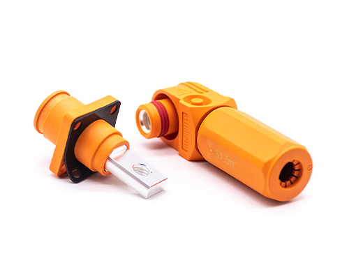
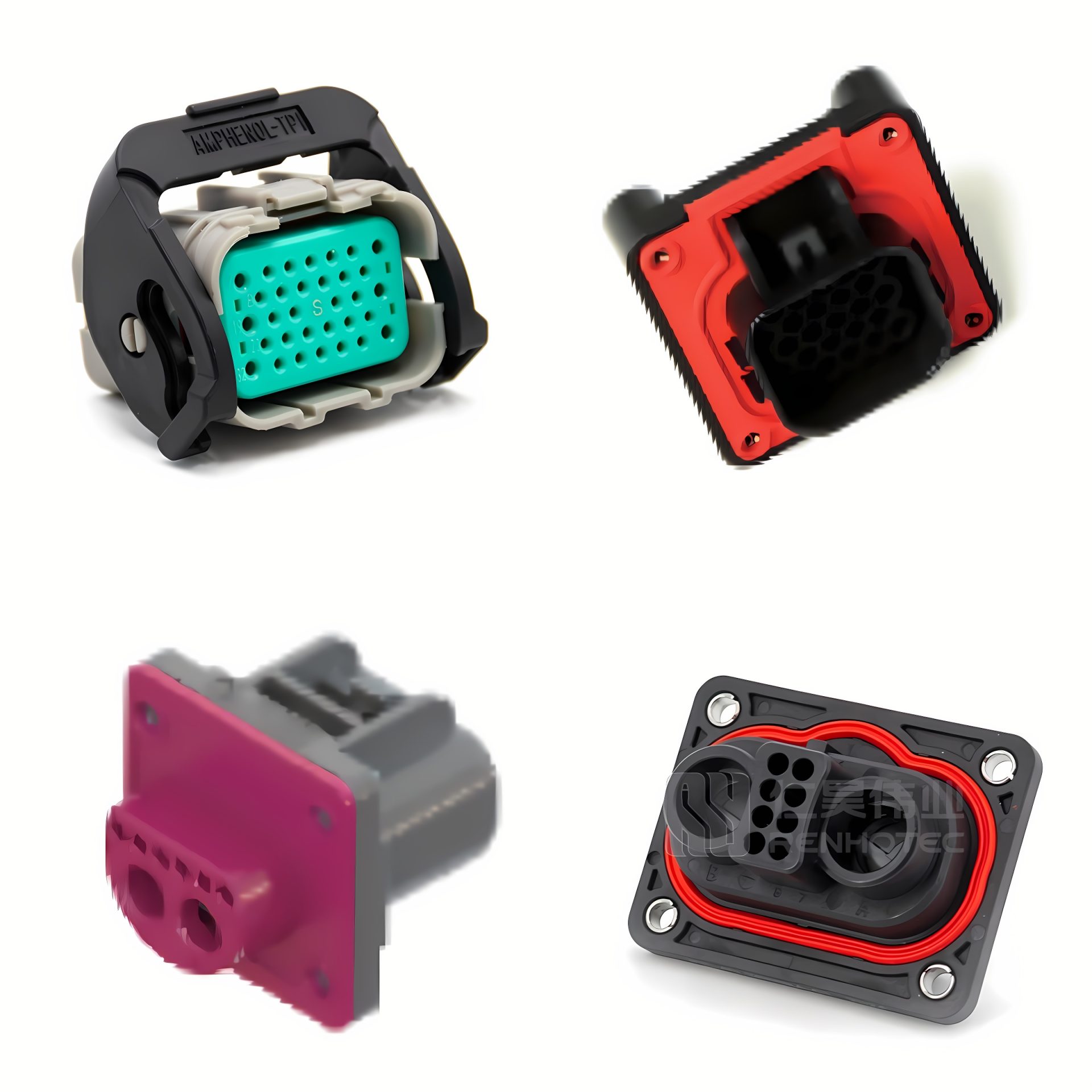
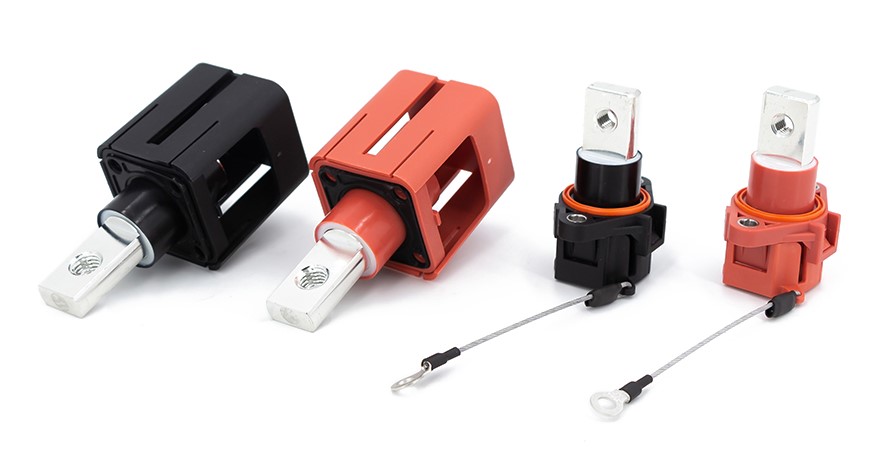
Beyond basic studs: HVIL-integrated connectors ensure maximum electrical safety in modern high-voltage architectures.
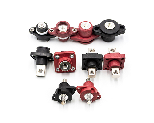
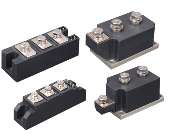
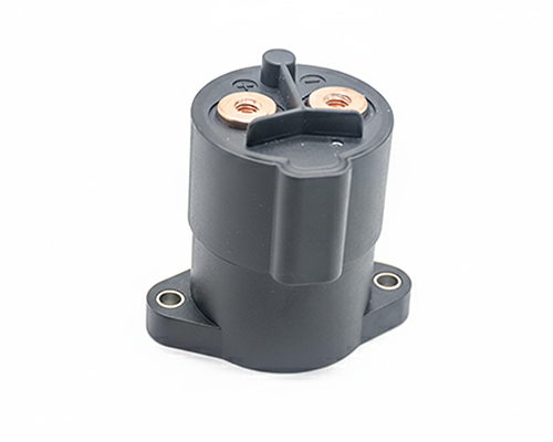
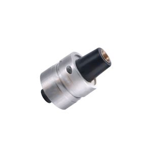
2. Material Science: Utilizing Certified Raw Materials
The choice of base material and plating is a primary factor in managing contact resistance.
Base Material (H62 Brass): As seen in our technical specs, we utilize H62 Brass (equivalent to ASTM C28000) for the stud body. This material offers a superior balance of tensile strength and electrical conductivity compared to pure copper, which can be prone to thread deformation under high torque.
PA66 Insulator: The housing utilizes high-grade PA66, which is engineered to meet UL94-V0 flammability standards. This material provides the necessary heat aging resistance to hold the stud securely even under significant vibration.
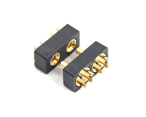
3. Advanced Design: Sealing and Anti-rotation Features
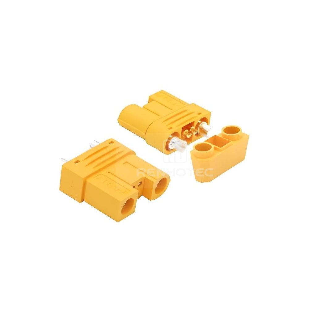
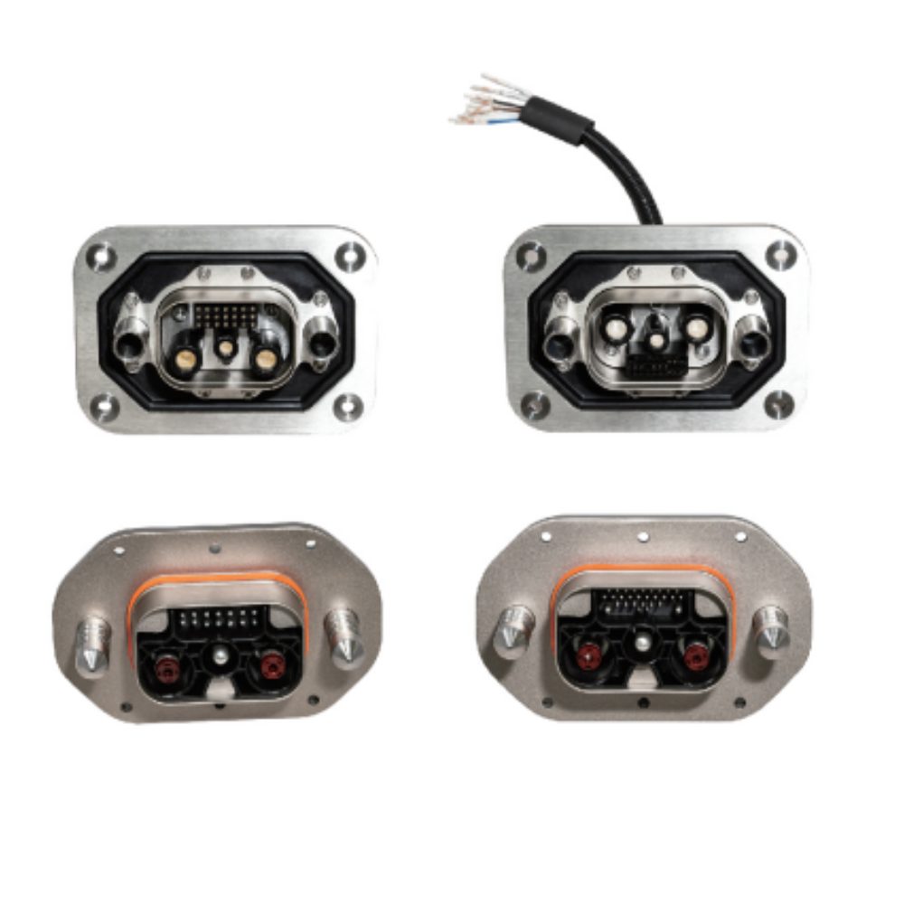
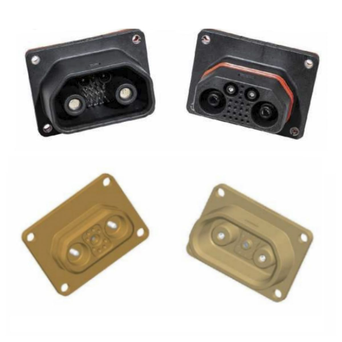
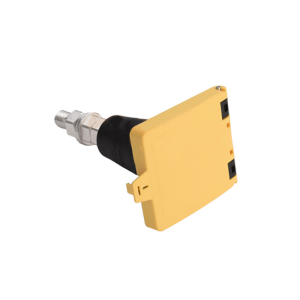
For integrated industry and trade businesses targeting global B2B clients, the Feed-through (Through-Wall) terminal is a high-demand item.
Sealing Integrity: To meet IP67 requirements, the interface between the terminal and the bulkhead must be precise. Achieving IP67 depends on proper gasket selection and controlled mounting surface roughness, following the 17.8mm diameter hole dimensions specified in our CAD drawings.
Anti-Rotation Design: To minimize the risk of the terminal rotating during nut tightening, our designs feature an orientation wedge or square-base flange designed to lock the unit into the chassis. This ensures that torque is applied only to the nut, maintaining the integrity of the environmental seal.
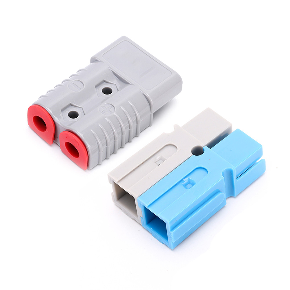
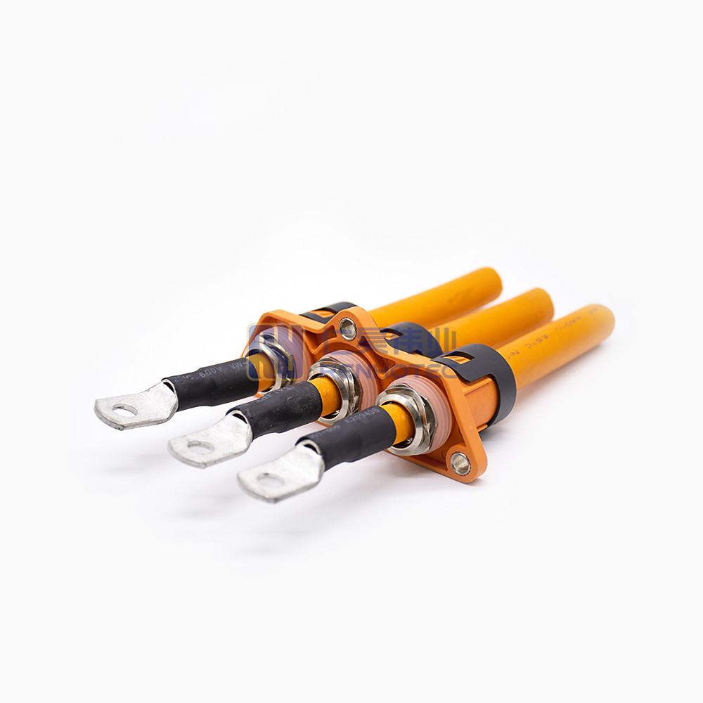
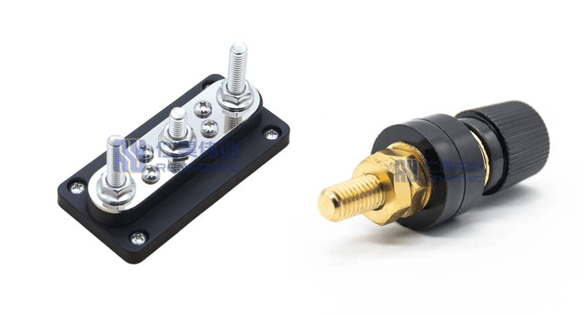
4. Installation Precision: Torque and Busbar Sizing
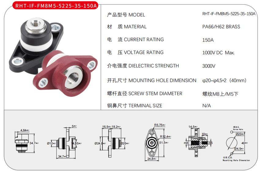
Technical specifications and mounting dimensions for the RHT-IF-FM8M5 series terminal stud.
A professional-grade terminal’s performance is highly dependent on its installation.
Torque Specifications: For M6 studs, typical target torque is 4.0 – 5.5 Nm; for M8, it is 8.0 – 10.0 Nm. Under-tightening increases resistance and the risk of arcing, while over-tightening can damage the threads.
Busbar Sizing: Use the formula S = I / 1.2 to ensure the connected cross-sectional area (S) can effectively manage the heat generated by the current (I).
Professional Interconnection
Selecting the right high-current terminal stud requires a holistic view of electrical loads and mechanical installation. By prioritizing technical parameters such as dielectric strength and anti-rotation properties, engineers can build systems that are not only efficient but also designed to be safe.
Need a full technical datasheet or other files for your project? Contact our sales engineer team by filling the following form today.