The Rectangular Connector is widely used in aerospace, medical instruments, consumer electronics (such as computers, TVs, game consoles, etc.), industrial control equipment, communication equipment, and automotive electronics. With its reliable connection performance, diverse specifications, and relatively convenient plug-in and unplug operations, it has become an indispensable component in various electronic and electrical applications.
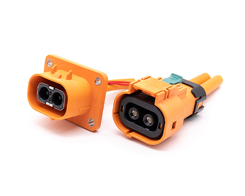
High Voltage Connectors are widely used in EV power systems, renewable energy installations, and industrial high-voltage circuits. Renhotec’s series drives the building of efficient, safe, and sustainable electrical ecosystems, meeting current technological demands.
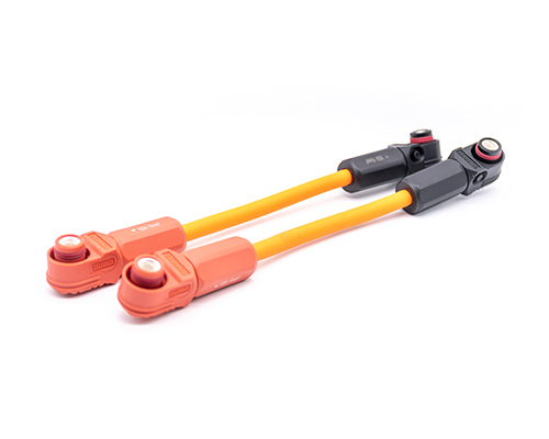
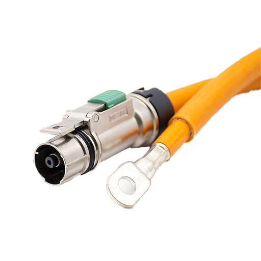
Renhotec EV Cable, crafted with top-notch conductive materials and meticulously engineered insulation, showcases outstanding impedance control and voltage-withstanding properties. Its design combines flexibility and durability to meet a wide array of installation needs. This cable is widely utilized in grid interconnections, large-scale industrial power supply systems, and high-voltage renewable energy projects, enabling smooth and efficient power transmission.
Renhotec, as a professional supplier, offers a comprehensive range of these Signal Transmission Connector products. Whether it is the high-reliability applications of the metal series or the wide adaptability of the plastic series in consumer electronic products, Renhotec can provide customers with high-quality options to meet the diverse requirements of signal transmission connections in different industries and scenarios.
Renhotec, active in electrical components, offers High Voltage DC Contactors in Epoxy Resin Sealing and Ceramic Sealing variants, with a 20A – 1000A current range. The Epoxy Resin Sealing one is cost-effective and protective. The Ceramic Sealing variant excels in thermal stability and insulation. They’re widely used in EV charging, renewable energy grid, and industrial high-voltage DC power distribution for reliable circuit control and current interruption, providing comprehensive solutions for multiple sectors.
Power Drawer Connector Design Guide: Managing Misalignment and High-Current Thermal Derating in Modular Systems
Designing modular power distribution systems (whether for energy storage units, server racks, or industrial drawers) is not as simple as matching the number of pins. (New to this technology? Start with our [Overview of Drawer Connectors] to understand the basics.) The real engineering challenge lies in ensuring connection reliability despite the unavoidable mechanical tolerances of the chassis and the thermal effects of high-current transmission.
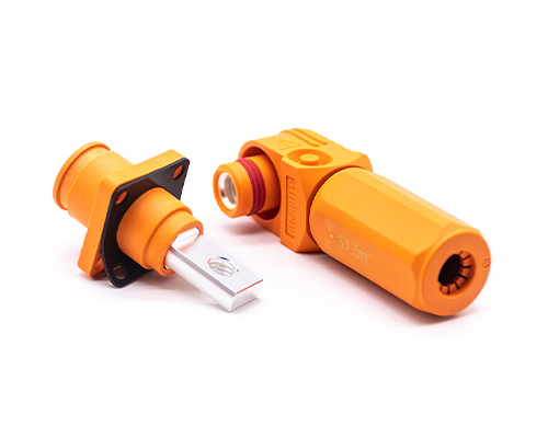
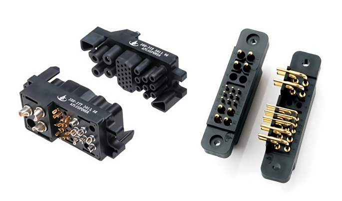
This guide explores the implementation logic of Renhotec’s power drawer connectors, utilizing advanced Crown Spring technology and Floating Mount structures to solve the industry’s two biggest pain points.
1. The Core Challenge: Blind Mating & Tolerance Stack-up
In a “blind mating” scenario, the operator cannot visually confirm whether the connectors are aligned. Relying on perfect mechanical alignment of the chassis is risky; the connector system itself must compensate for the cumulative tolerances (Tolerance Stack-up) of the rack and drawer.
How “Floating Mount” Solves Radial Misalignment
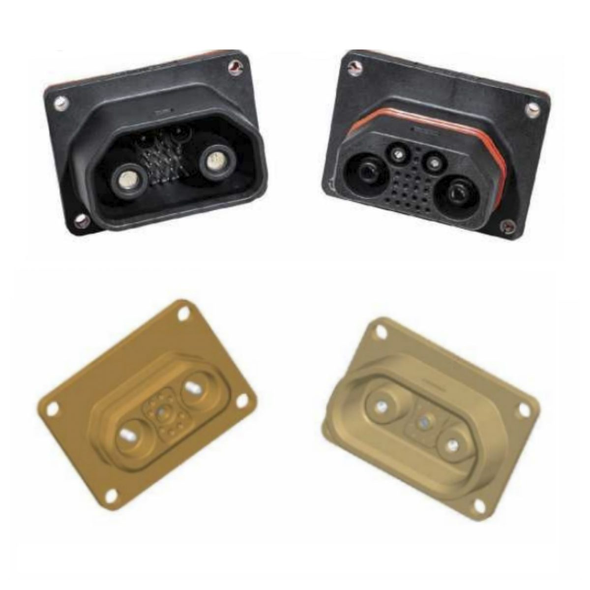
Standard rack manufacturing tolerances can deviate by ±1.0mm or more. To prevent insulator cracking or pin damage, our power drawer connector series utilizes a Floating Mount Design.
The Mechanism: As detailed in our design specifications, the connector employs specialized floating rivets or shoulder screws on the mounting flange.
The Benefit: This allows the connector to “self-align” by moving radially (X/Y axis) within the panel cutout. It effectively absorbs the manufacturing errors of the sheet metal, ensuring the pins enter the sockets smoothly without mechanical stress.
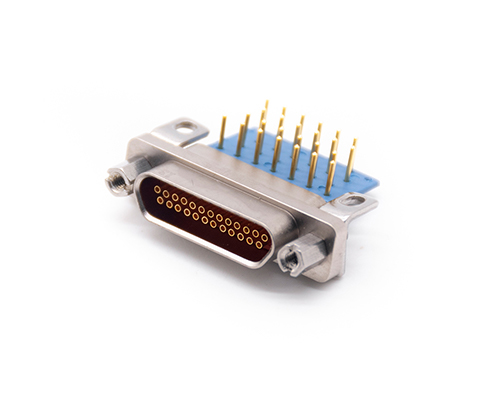
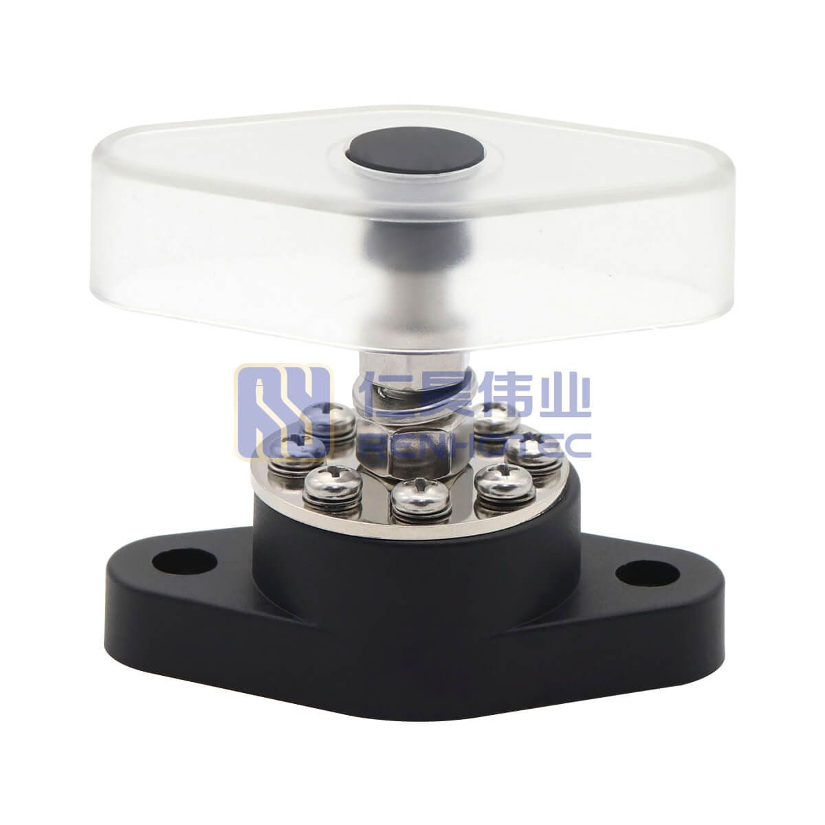
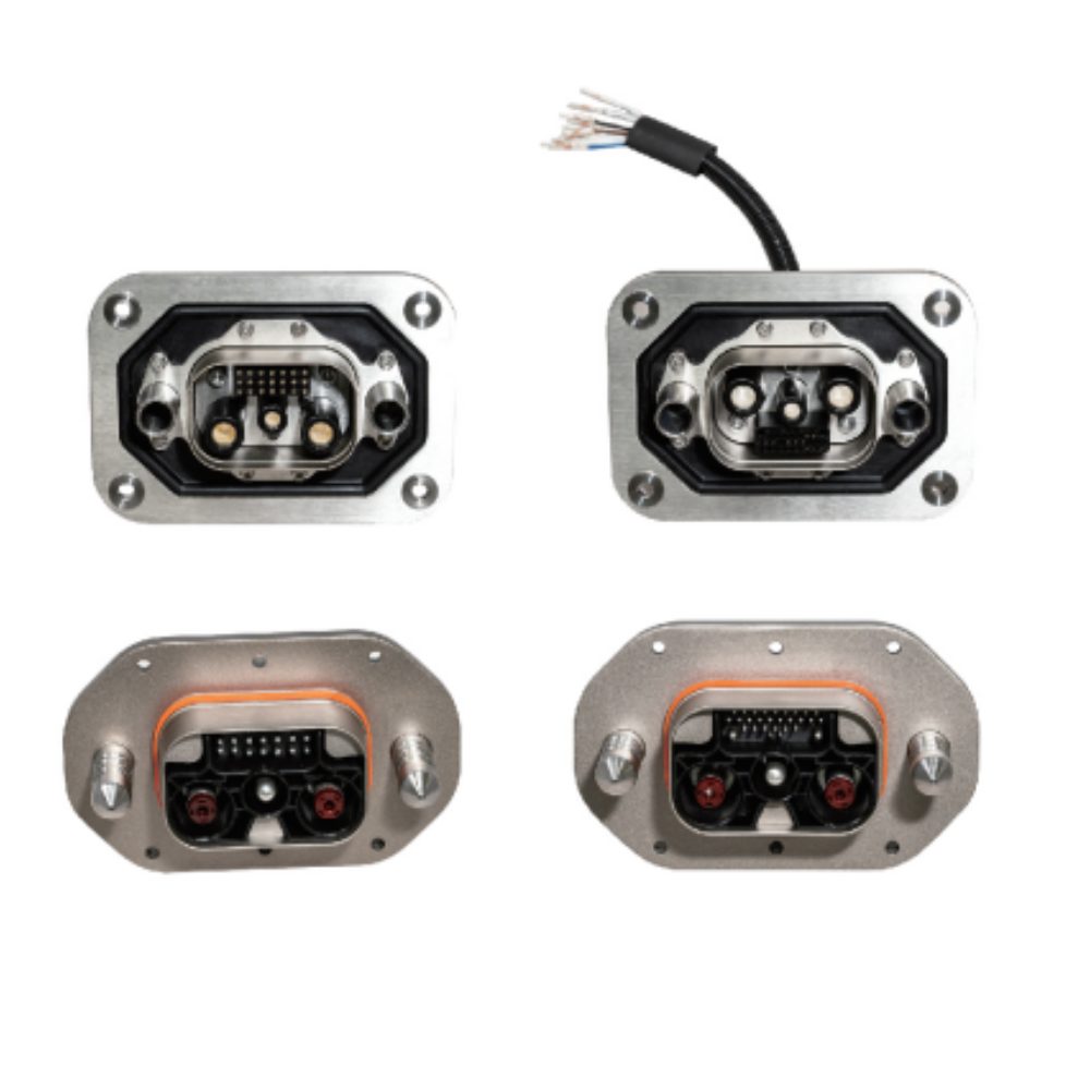
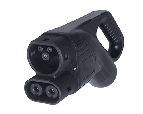
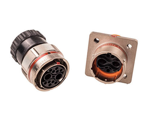
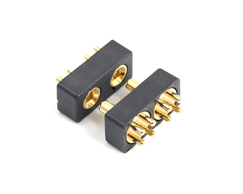
Power Drawer Connectors
2. Low Contact Resistance: The “Crown Spring” Advantage
Heat is the enemy of any high-current system. In a confined drawer space, high contact resistance leads to temperature rise (Joule heating), which can degrade insulators over time.
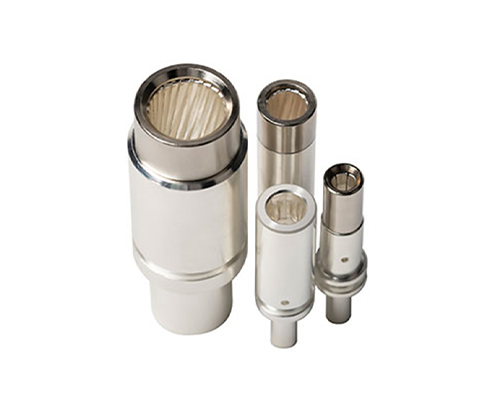
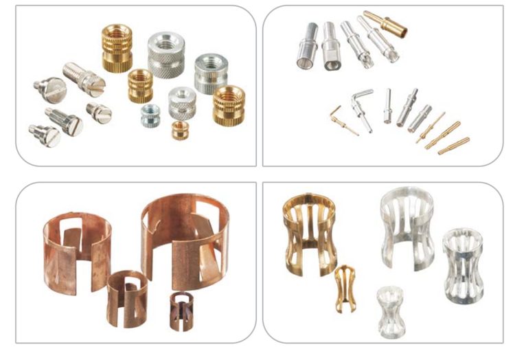
Instead of standard leaf springs, Renhotec utilizes Crown Spring (Jack) technology in our socket contacts.
Why Crown Springs Matter for Thermal Management:
Multi-Point Contact: The unique cage-like structure of the crown spring ensures multiple louvers touch the pin simultaneously, significantly increasing the effective contact area.
Low Resistance: More contact area means lower contact resistance. Lower resistance means less heat generation ($P=I^2R$) compared to traditional split-tine designs.
Vibration Resistance: The elastic nature of the crown spring maintains constant normal force even under high vibration, preventing micro-arcing and fretting corrosion.
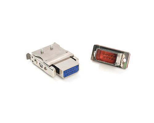
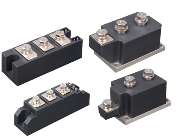
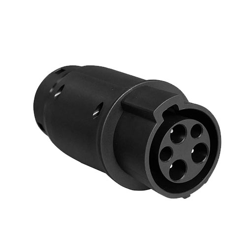
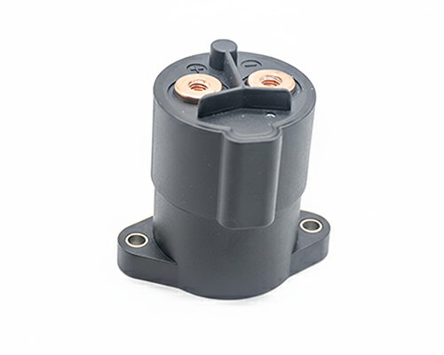
Contacts with Gold / Silver Plating
3. Understanding Thermal Derating
While a connector may be rated for “150A” or “350A”, this rating is typically based on ideal conditions (e.g., 20°C ambient). In real-world modular systems, engineers must calculate based on the Derating Curve.
The “All Contacts Energized” Factor
When integrating a multi-pin drawer connector, grouping high-current conductors creates mutual heating.
Engineering Rule: As ambient temperature rises (e.g., inside a working server rack), the safe current carrying capacity decreases.
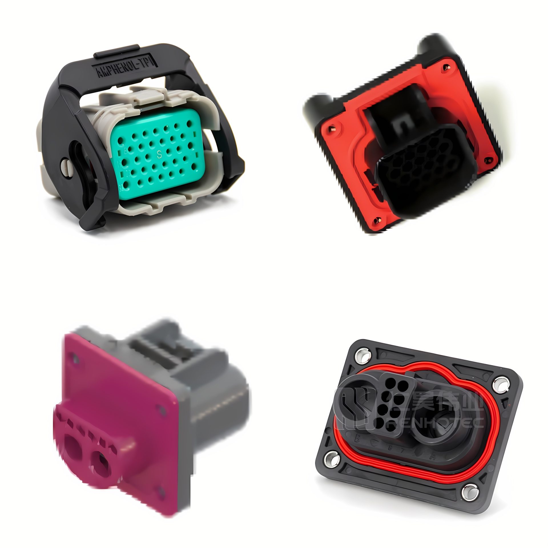
Design Recommendation: We recommend operating at 80% of the rated current for continuous loads to ensure a sufficient thermal safety margin.
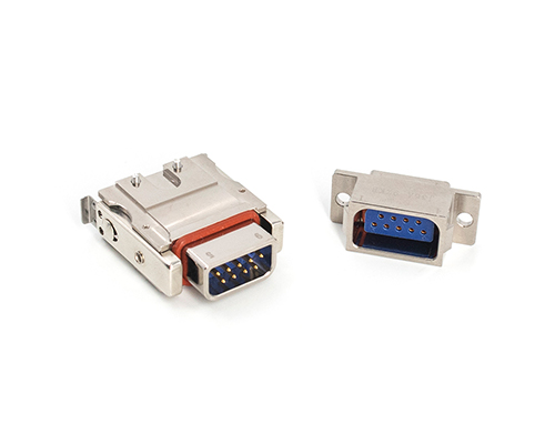
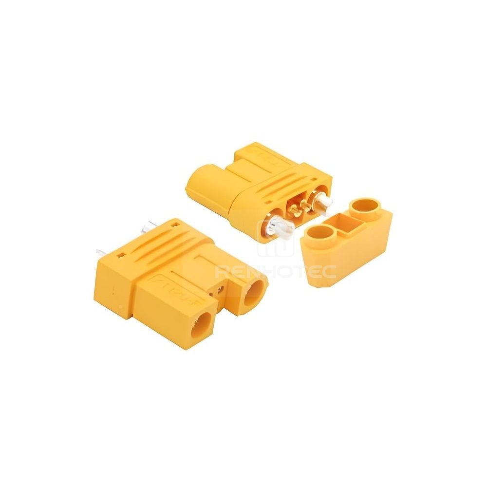
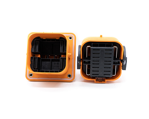
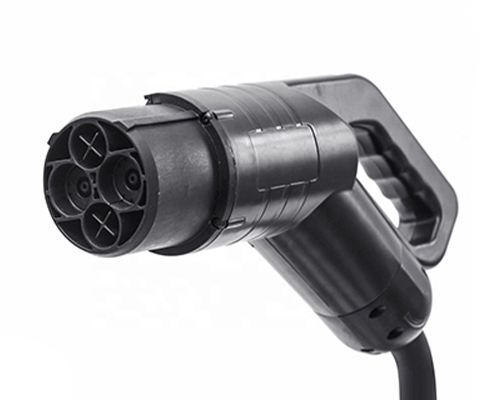
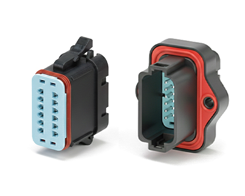
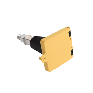
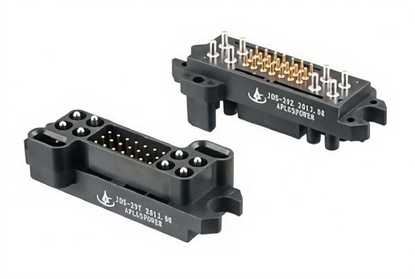
Power Drawer Connectors
4. Integration Guide: Panel Cutout & Termination
Successful integration relies on correct panel preparation. A common error is restricting the connector’s movement, effectively nullifying its floating capability.
Panel Cutout Strategy
To allow the connector to float:
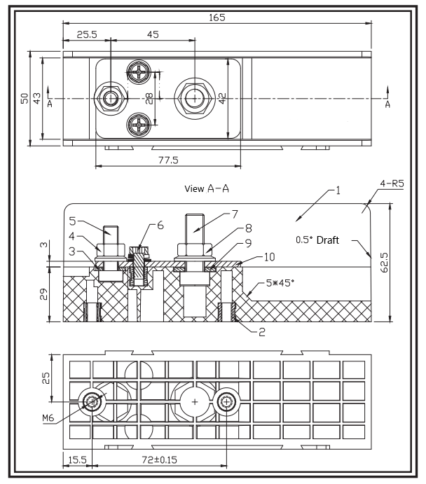
Oversized Cutout: The hole in your panel must be slightly larger than the connector body (refer to the tolerance values in our drawing).
Correct Fastening: When mounting, ensure the floating mechanism is not clamped tight. The connector should have slight “play” to adjust itself during mating.
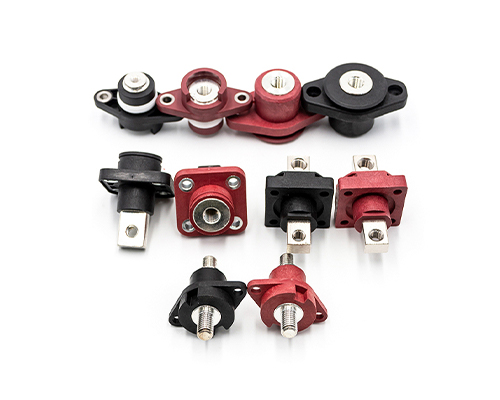
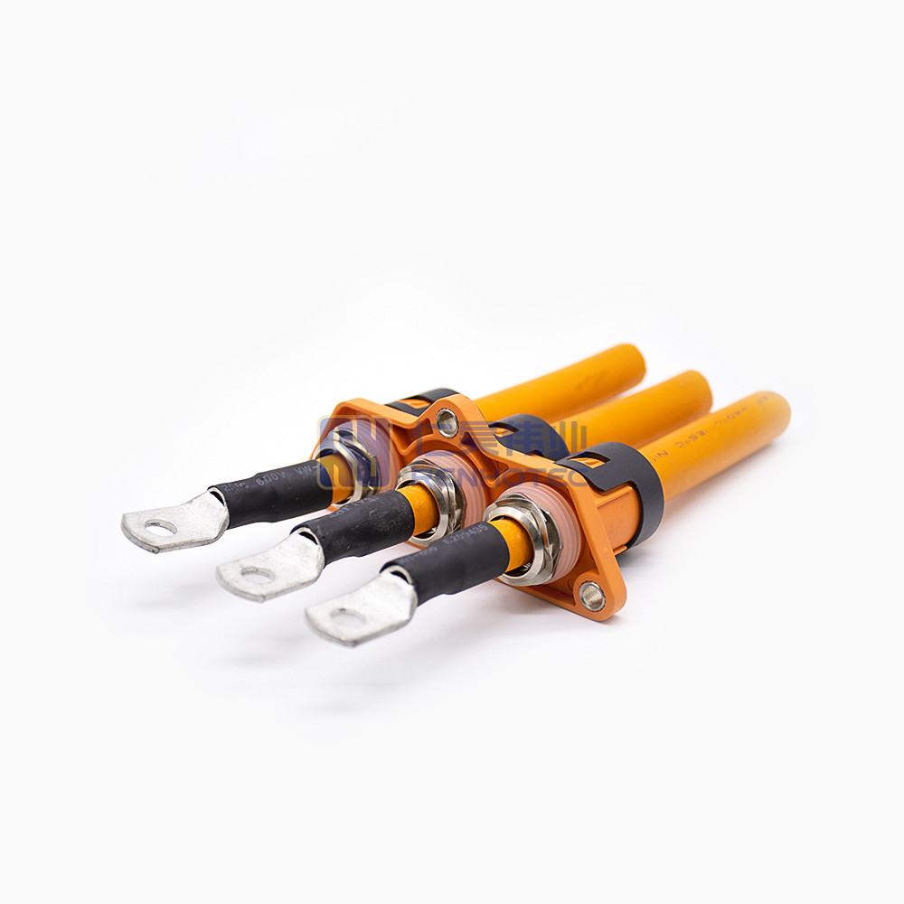
Termination Options
We offer a variety of termination options to suit your assembly needs:
Crimp Type: Best for high-volume cable assembly, providing a gas-tight seal and vibration resistance.
PCB Tail: For direct board-to-board power distribution.
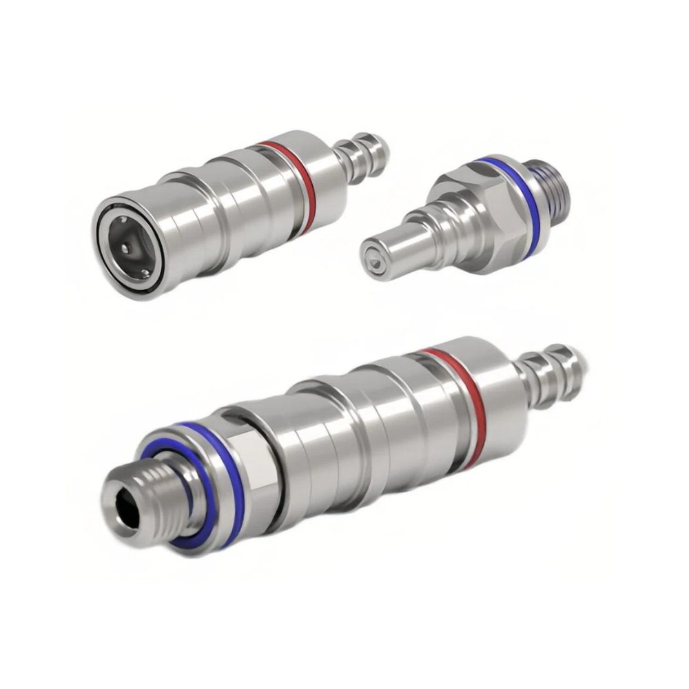
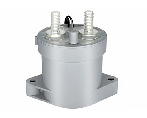
Threaded/Busbar: For ultra-high current applications (e.g., 150A+).
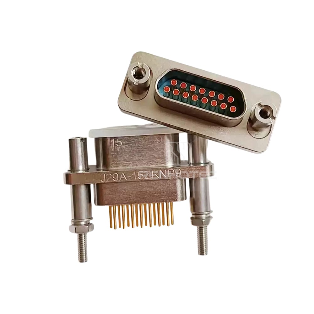
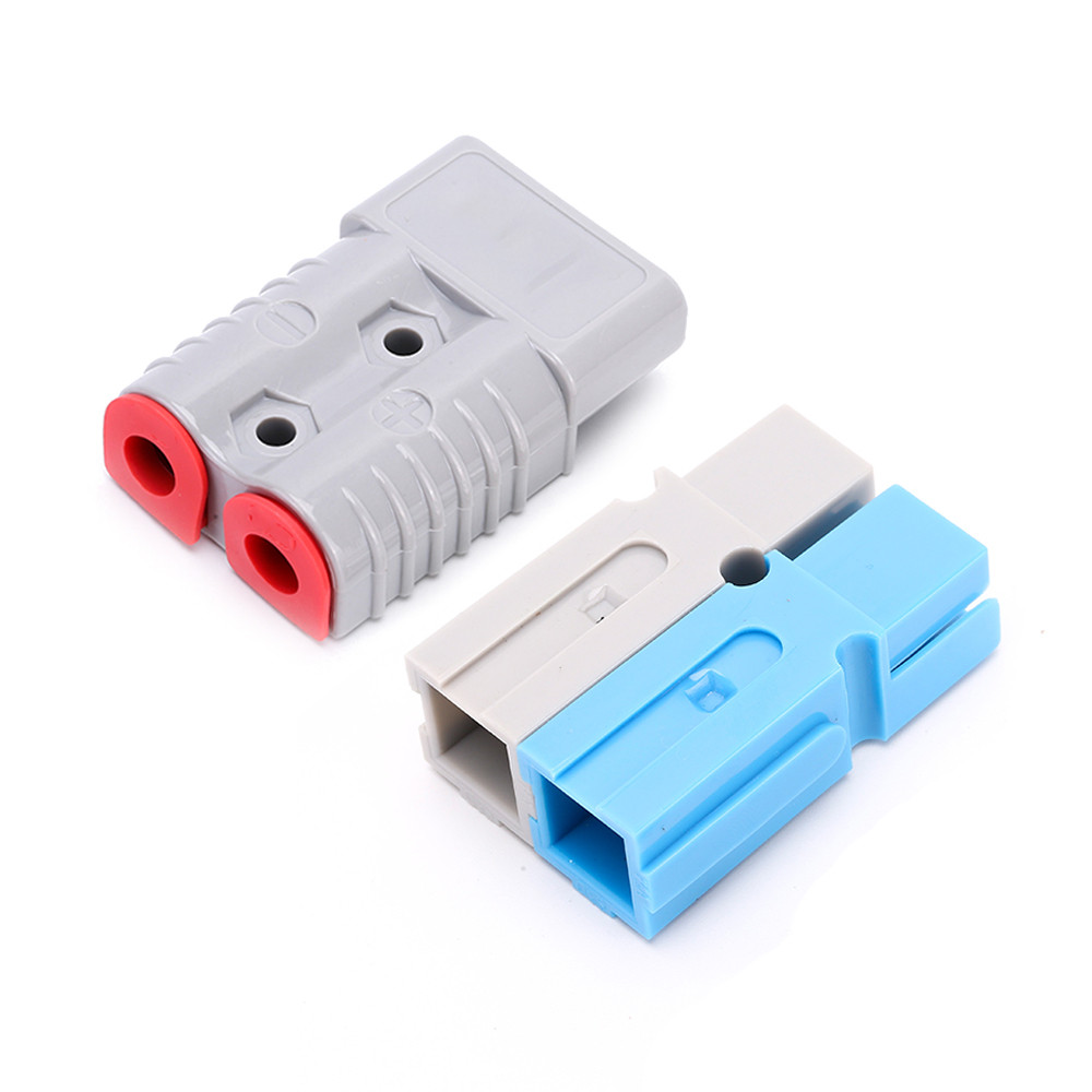
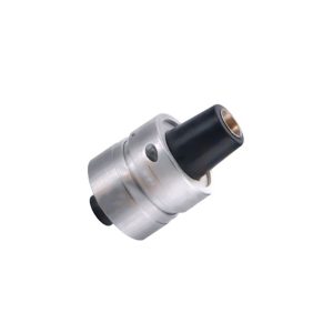
Installation Dimensions Example
5. Quick Design Checklist
Before finalizing your drawer design, ensure you have checked:
Float Calculation: Does your panel cutout allow enough radial movement (> ±1.0mm) for the chassis tolerance?
Current Headroom: Have you applied the 20% derating factor for the expected ambient temperature?
Cable Strain: Is the cable terminated with enough slack to allow the connector to float freely?
FAQ – Power Drawer Connector Engineering
Can Renhotec power drawer connectors be used for Hot Swapping?
Yes, but with design considerations. While the Crown Spring design is robust, for maximum safety at full load, we recommend implementing a “Last-Mate, First-Break” loop (using shorter detection pins) or an external interlock circuit. This prevents arcing during disconnection and extends contact life.
What is the benefit of Silver Plating for high-current connectors?
For high-current applications, we recommend Silver Plating. Silver has the highest electrical conductivity of any metal, offering lower contact resistance and better thermal performance than Gold or Tin. This is critical for minimizing heat accumulation in enclosed modular drawers.
How much misalignment can the floating mount handle?
The Renhotec Power Drawer Series is designed to accommodate approximately ±1.0mm of radial (X/Y axis) misalignment. The floating rivets allow the connector body to self-align within the panel cutout, compensating for chassis tolerances during blind mating.
How do I determine the correct panel cutout size?
The panel cutout must be slightly larger than the connector body to allow for floating movement. Please download the specific datasheet for your model (e.g., CD Series) to get the exact tolerance dimensions for the cutout and mounting holes.
Ready to Optimize Your Modular Design?
Don’t let misalignment compromise your system’s reliability.
[Contact Engineering]: Unsure how to select the right power drawer connector for your project? Contact our sales engineering team for a consultation and specific technical data.