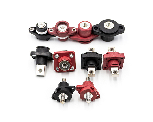
The Rectangular Connector is widely used in aerospace, medical instruments, consumer electronics (such as computers, TVs, game consoles, etc.), industrial control equipment, communication equipment, and automotive electronics. With its reliable connection performance, diverse specifications, and relatively convenient plug-in and unplug operations, it has become an indispensable component in various electronic and electrical applications.
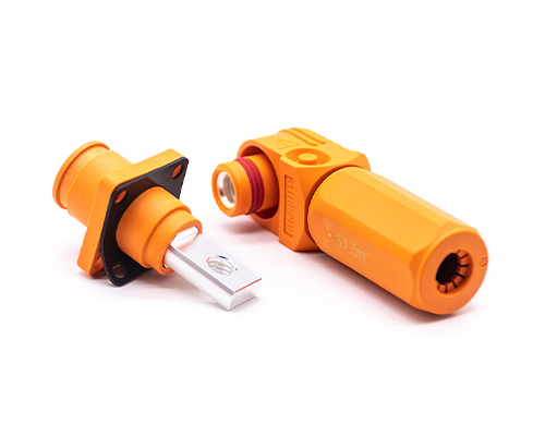
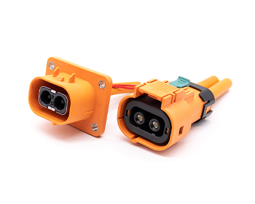
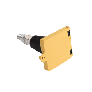
High Voltage Connectors are widely used in EV power systems, renewable energy installations, and industrial high-voltage circuits. Renhotec’s series drives the building of efficient, safe, and sustainable electrical ecosystems, meeting current technological demands.
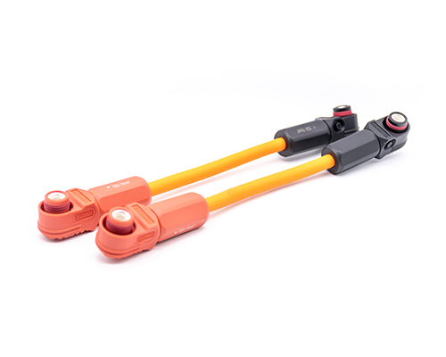
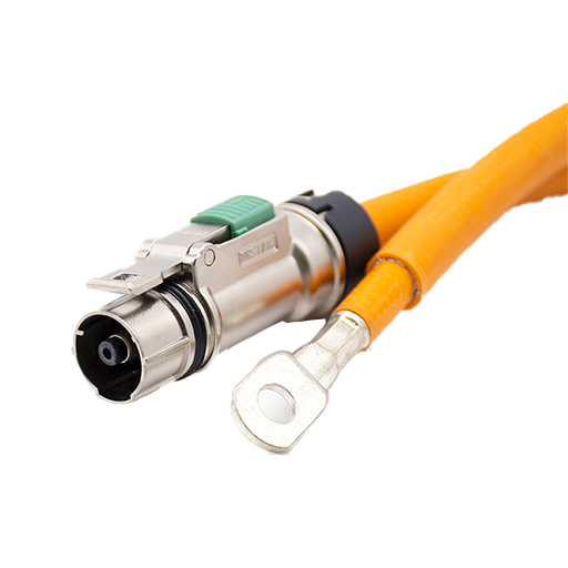
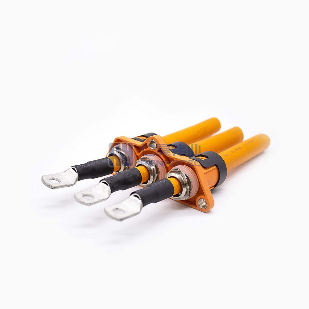
Renhotec EV Cable, crafted with top-notch conductive materials and meticulously engineered insulation, showcases outstanding impedance control and voltage-withstanding properties. Its design combines flexibility and durability to meet a wide array of installation needs. This cable is widely utilized in grid interconnections, large-scale industrial power supply systems, and high-voltage renewable energy projects, enabling smooth and efficient power transmission.
Renhotec, as a professional supplier, offers a comprehensive range of these Signal Transmission Connector products. Whether it is the high-reliability applications of the metal series or the wide adaptability of the plastic series in consumer electronic products, Renhotec can provide customers with high-quality options to meet the diverse requirements of signal transmission connections in different industries and scenarios.
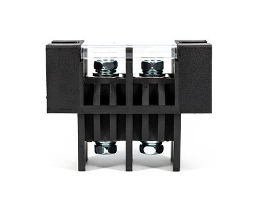
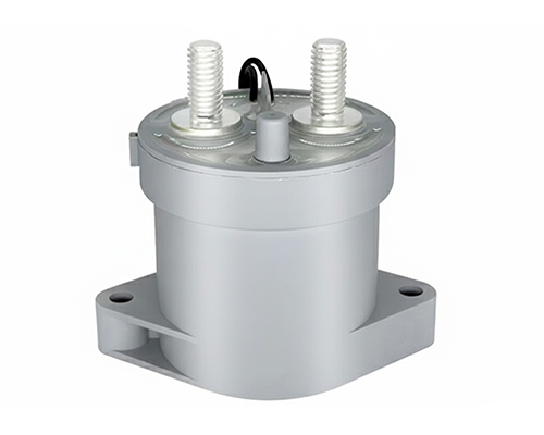
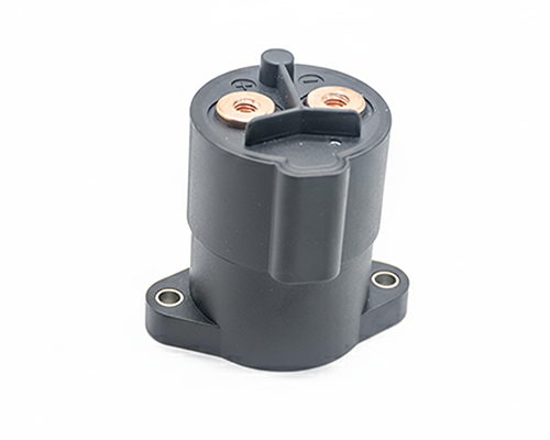
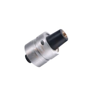
Renhotec, active in electrical components, offers High Voltage DC Contactors in Epoxy Resin Sealing and Ceramic Sealing variants, with a 20A – 1000A current range. The Epoxy Resin Sealing one is cost-effective and protective. The Ceramic Sealing variant excels in thermal stability and insulation. They’re widely used in EV charging, renewable energy grid, and industrial high-voltage DC power distribution for reliable circuit control and current interruption, providing comprehensive solutions for multiple sectors.
Modern electronic systems are increasingly constrained by SWaP-C considerations (Size, Weight, Power, and Cost). In industries such as aerospace avionics, medical imaging systems, advanced industrial automation, and now, AI-driven High-Performance Computing (HPC) and autonomous vehicle networks, the interconnect layer has become a critical component in overall system reliability.
Engineering teams frequently face a persistent design challenge: as system complexity increases, the number of signal channels grows while the available panel and PCB space remains limited.
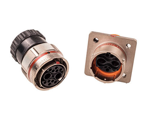
Traditional circular connectors remain mechanically robust and widely used, but their geometry can reduce panel space utilization when multiple connectors must be installed in dense arrays.
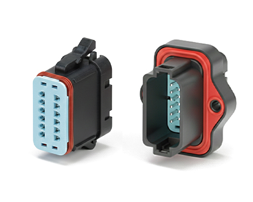
For this reason, rectangular connector architectures have become widely adopted in modern electronic systems, particularly where compact layout and high contact density are required.
This comprehensive rectangular connector guide provides an engineering overview of rectangular connector technologies, examining connector geometry, contact mechanics, materials, and relevant industry standards.
2. Connector Geometry and Space Efficiency
The transition from circular connectors to rectangular connectors is primarily driven by improvements in panel space utilization and PCB routing efficiency.
Rectangular vs Circular Connector Space Utilization
Feature
Circular Connector
Rectangular Connector
Panel Packing
Circular footprints create unused gaps between connectors
Rectangular connectors can often achieve higher packing efficiency when installed in arrays because their straight edges allow connectors to align closely with each other.
This layout advantage enables engineers to route a greater number of signals through the same panel area.
PCB Routing Advantages
The linear arrangement of contacts in rectangular connectors simplifies PCB routing.
Designers can route signal traces directly away from connector rows, reducing the number of required vias and simplifying multilayer PCB design.
This is particularly valuable in high-density systems such as avionics modules or embedded control units.
Mechanical Polarization
Preventing mismating is critical in multi-contact connector systems.
Circular connectors typically rely on internal keying features to ensure correct mating orientation.
This design approach is useful in blind-mate applications such as rack-mounted electronics.
Asymmetric Housing Geometry of Rectangular Connector
3. Contact Mechanics and Failure Mode Analysis
The long-term reliability of electrical connectors depends heavily on the mechanical behavior of their contact interfaces.
In vibration-prone environments, microscopic movement between contacts can lead to degradation over time.
Fretting Corrosion
Fretting corrosion occurs when small oscillatory motions between contact surfaces repeatedly disrupt oxide layers on metal surfaces.
This process generates oxidized debris that accumulates at the contact interface and increases contact resistance.
If severe enough, fretting corrosion can cause intermittent electrical connections.
Connector designs that maintain stable contact force and multiple contact points can help reduce this risk.
Common Contact Architectures
Contact Technology
Engineering Principle
Advantages
Limitations
Machined Solid Pin
Cylindrical pin and socket interface
High current capacity
Vibration tolerance depends on socket design
Stamped & Formed Contacts
Metal sheet formed into spring contacts
High manufacturing efficiency
Moderate durability
Twist-Pin Contacts
Multiple spring wires forming contact interface
Excellent vibration resistance
Higher manufacturing complexity
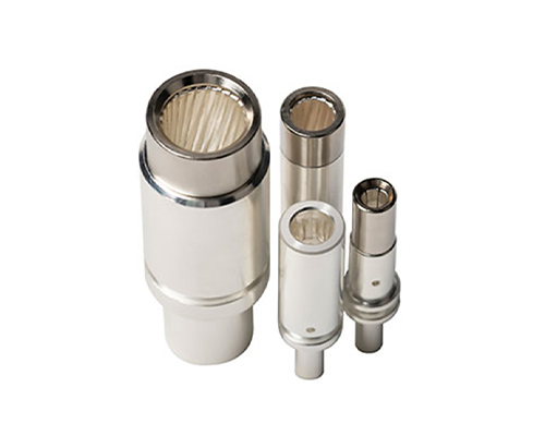
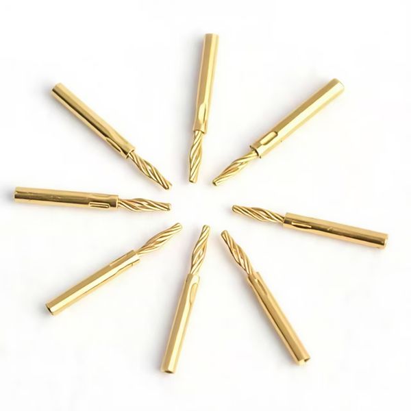
Twist-Pin Contact Design
Twist Pin of Rectangular Connector
Twist-pin contacts are formed by multiple spring wires arranged around a central core.
When inserted into a socket contact, the spring wires compress and generate radial force.
This creates multiple electrical contact points simultaneously. If vibration disrupts one contact interface momentarily, other contact points maintain electrical continuity.
Because of this redundancy, twist-pin contacts are commonly used in aerospace, defense, and other mission-critical electronic systems.
4. Material Selection for Connector Performance
Connector reliability depends strongly on the materials used for contacts, insulators, and connector shells.
Contact Materials
Electrical contacts must balance conductivity with mechanical elasticity.
Beryllium Copper (BeCu) is widely used in high-performance connectors due to its combination of conductivity, strength, and resistance to stress relaxation.
BeCu contacts maintain their spring force after repeated mating cycles and temperature exposure.
Phosphor Bronze is often used in commercial electronics where cost efficiency is a higher priority.
Insulator Materials
Connector insulators must isolate contacts electrically while maintaining mechanical stability.
Common materials include glass-filled thermoplastics such as: Polyphenylene Sulfide (PPS) and Polybutylene Terephthalate (PBT).
Glass reinforcement improves dimensional stability and heat resistance during soldering.
Most industrial connectors meet UL94 V-0 flame retardancy standards.
Contact Plating
Connector contacts are commonly plated with gold over nickel.
Gold provides corrosion resistance and stable electrical conductivity, while the nickel underlayer acts as a diffusion barrier.
Connector shells made from aluminum alloy are often plated with electroless nickel for corrosion resistance and electromagnetic shielding.
5. Industry Standards and Qualification Testing
Connector performance is typically validated through standardized testing procedures.
MIL-DTL-83513 (Micro-D Connectors)
MIL-DTL-83513 defines dimensional and performance requirements for Micro-D rectangular connectors with a 1.27 mm contact pitch.
Typical qualification tests include:
Thermal cycling between −55°C and +125°C
Mechanical vibration testing
Mechanical shock testing
Salt spray corrosion testing
These tests ensure connector performance in demanding environments.
GJB2446
GJB2446 is a Chinese military standard that defines general performance and testing requirements for micro-rectangular electrical connectors used in defense and aerospace electronics.
The standard specifies environmental, electrical, and mechanical verification procedures similar to other military connector standards.
RoHS and REACH Compliance
Commercial connectors must comply with environmental regulations such as:
RoHS (Restriction of Hazardous Substances)
REACH (Registration, Evaluation, Authorization and Restriction of Chemicals)
These regulations restrict the use of hazardous substances in electronic components.
6. How to Choose a Rectangular Connector?
Selecting an appropriate connector requires evaluating several engineering factors. Before advancing to specific implementation models, engineering and purchasing teams must evaluate their system parameters against the decision matrix in this rectangular connector guide:
Design Requirement
Key Considerations
PCB Space
Contact pitch and connector footprint
Current Load
Contact size and wire gauge
Environmental Conditions
Vibration, shock, temperature
Mounting Method
Through-hole vs surface mount
Maintenance Needs
Mating cycle durability
Proper connector selection balances electrical performance, mechanical durability, and system integration constraints.
Rectangular Connectors
7. Example Connector Architectures in the Market
To bridge the gap between theoretical standards and supply chain reality, it is essential to examine how these architectures are implemented by leading global manufacturers. The market is populated by various series that cater to specific tiers of the engineering decision matrix, establishing the baselines for cross-brand intermateability.
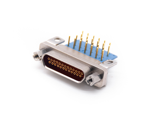
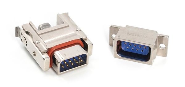
The Micro-D Standard Architecture (1.27mm Pitch)
Designed to meet the strict parameters of the MIL-DTL-83513 standard, these connectors are the default choice for aerospace flight controllers, missile guidance systems, and lightweight tactical equipment operating within a -55°C to +125°C temperature window.
Market Examples: Glenair MWTM Series, AirBorn M-Series, ITT Cannon MDM Series, and Renhotec J30J Series.
Implementation Note: These series typically utilize CNC-machined aluminum alloy shells for exceptional EMI shielding. They heavily rely on twist-pin or highly elastic contact technology to support up to 100 cores (leading manufacturers have pushed this architectural boundary to 128, eg. Molex Airborn M-Series). This architecture represents a highly reliable, cross-compatible solution capable of maintaining an insulation resistance of ≥ 5000M Ohms and a dielectric withstand voltage of 600V to 800V AC.
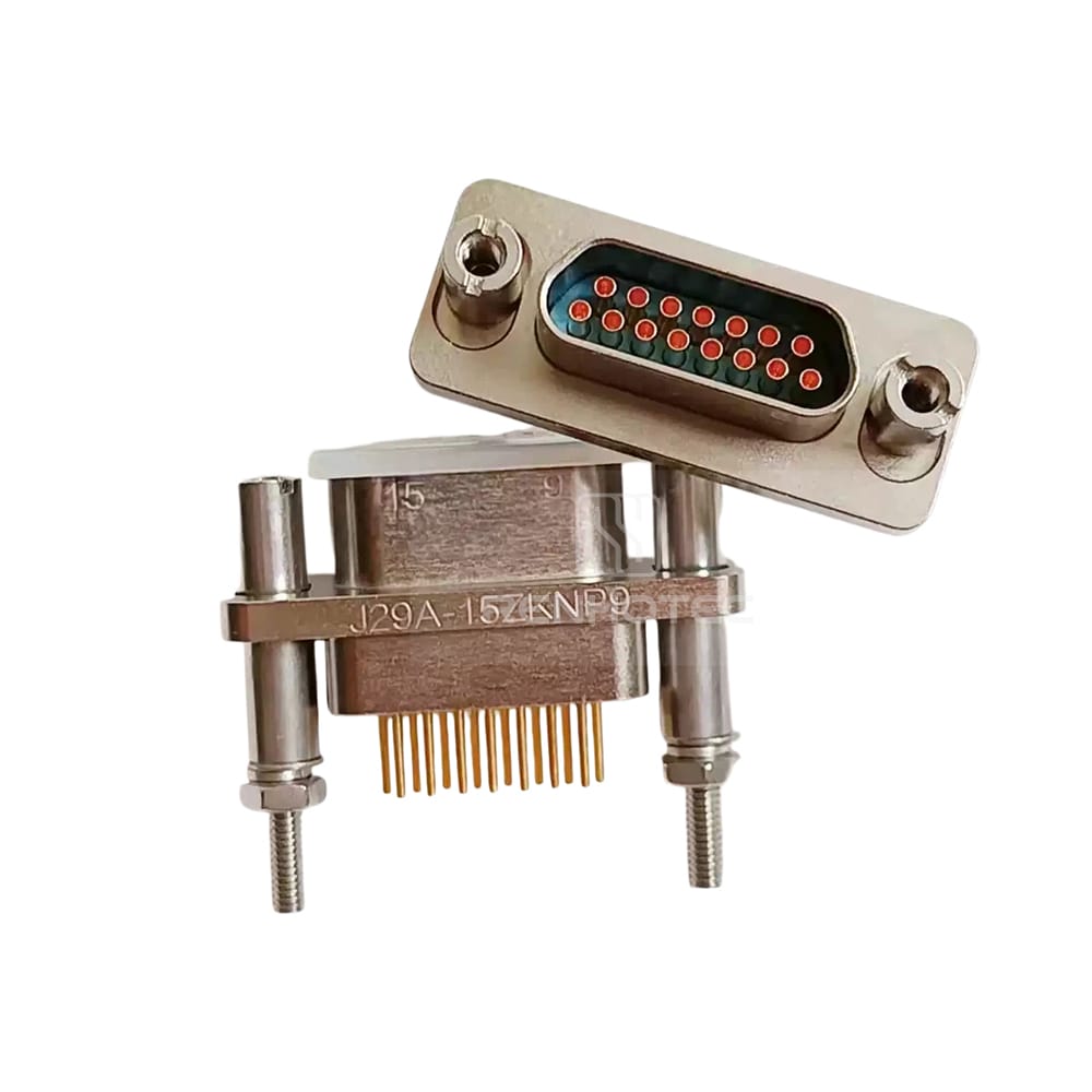
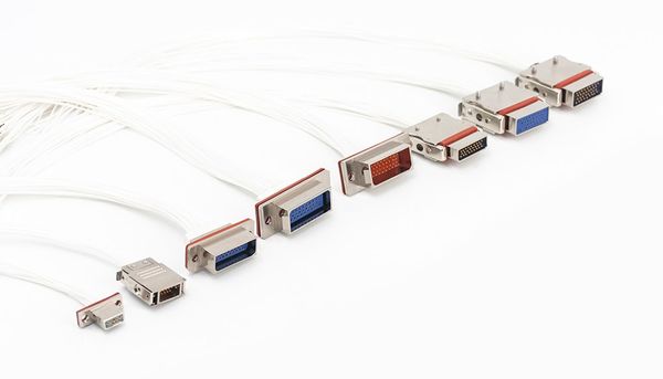
High-Density and Nano-D Derivatives (0.635mm to 1.91mm Pitch)
This architecture addresses the engineering gap where standard Micro-D density is still too large for ultra-compact payloads, or where customized pitch spacing is required for specific current-carrying thresholds.
Implementation Note: Nano-D systems push miniaturization to the absolute limit with a 0.635mm pitch, typically utilizing specialized spring-pin contacts. Conversely, derivative high-density systems (such as 1.91mm pitch variants) offer a middle-ground geometry. By leveraging the increased physical spacing, they exceed the standard 3A rated current of traditional Micro-D systems, offering higher current carrying capacity while accommodating wire cross-sectional areas up to 0.3mm². These are heavily utilized in satellite avionics and UAV payloads.
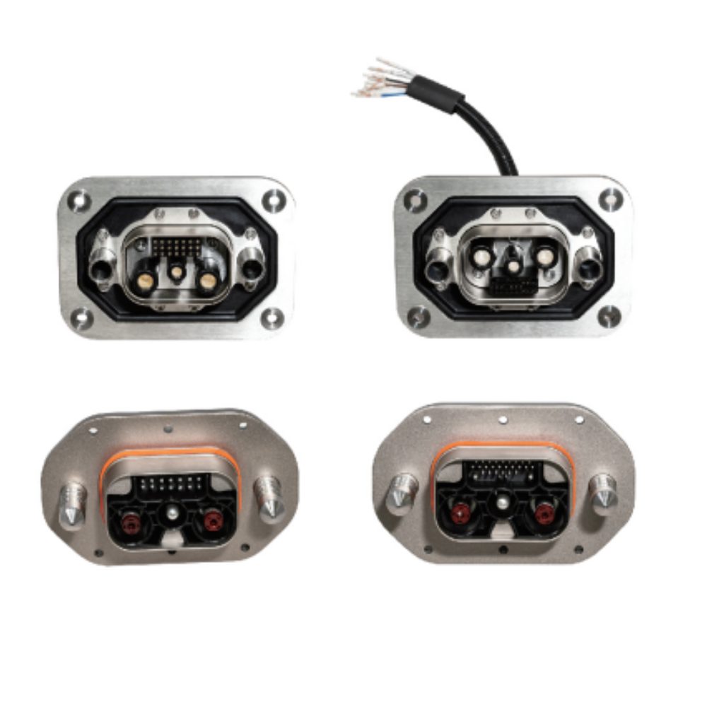
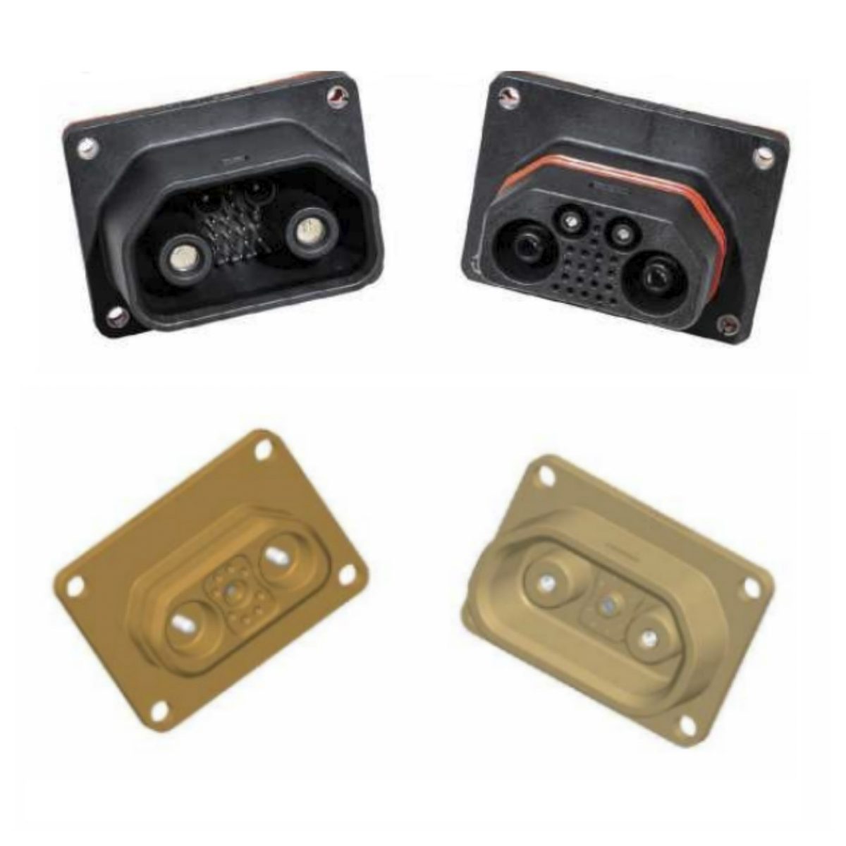
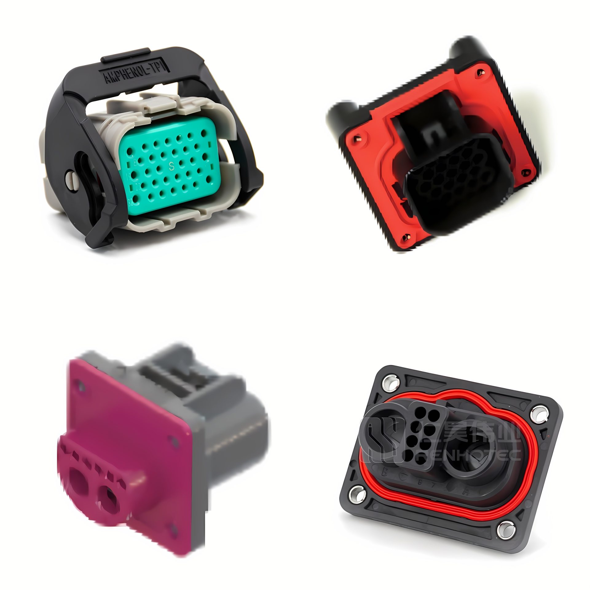
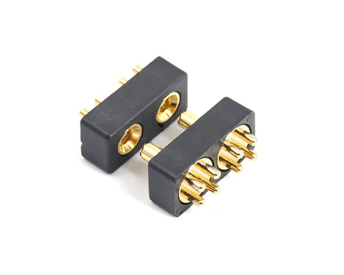
Industrial Signal/Power Hybrids
Shifting focus to high-density commercial, medical (MRI/CT), and industrial automation, these connectors abandon heavy metal shells in favor of lightweight, Glass-Filled Thermoplastic UL94V-0 moldings.
Implementation Note: Available in 2.0mm, 3.0mm, and 4.0mm spacing configurations, these series utilize high-reliability 4-finger Beryllium Copper (BeCu) inner contacts to combat fretting corrosion. Their defining feature is hybrid technology integration—combining low-current signal transmission with high-current power delivery within a single connector block. This architecture is increasingly vital for edge AI robotics and autonomous vehicle domain controllers, where compact space maximization is necessary but extreme shock resistance (compared to military specs) is secondary.
Rectangular Connector Application – AI Robot
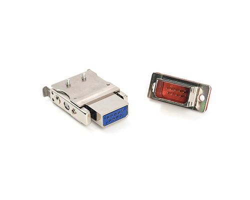
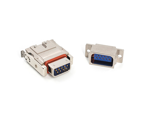
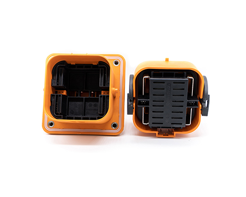
Modular Rack and Panel Architectures
Engineered specifically for blind-mating inside dark, confined environments, these connectors are the backbone of AI data center server racks, power distribution units (PDUs), and drawer-style control cabinets.
Implementation Note: These systems prioritize mechanical ruggedness over extreme miniaturization. They feature robust guide pins, float-mount capabilities to absorb tolerance stack-ups, and often incorporate double insurance locking mechanisms to guarantee high reliability during insertion. Terminations include heavy-duty crimp, solder cup, or direct straight printed board (PCB) mounting.
Section 8: Supply Chain and Customization
Connector deployment often requires customization beyond standard catalog configurations.
Wire Harness Integration
Many suppliers offer pre-wired connector assemblies, which simplify system integration and reduce manual soldering during final assembly.
Wire gauges are typically selected according to current requirements.
Mounting Configurations
Rectangular connectors are available in multiple PCB mounting orientations:
Vertical (straight) mounting
Right-angle mounting
Selecting the correct configuration helps optimize internal system layout.
Quality Assurance
High-reliability connector production usually includes batch testing for parameters such as:
Insulation resistance
Dielectric withstand voltage
Electrical continuity
These verification procedures help ensure connectors meet specified performance requirements before shipment.
We hope this rectangular connector guide has provided you with the clarity needed to navigate the demanding requirements of modern electronics.