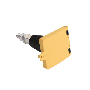
The Rectangular Connector is widely used in aerospace, medical instruments, consumer electronics (such as computers, TVs, game consoles, etc.), industrial control equipment, communication equipment, and automotive electronics. With its reliable connection performance, diverse specifications, and relatively convenient plug-in and unplug operations, it has become an indispensable component in various electronic and electrical applications.
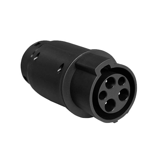
High Voltage Connectors are widely used in EV power systems, renewable energy installations, and industrial high-voltage circuits. Renhotec’s series drives the building of efficient, safe, and sustainable electrical ecosystems, meeting current technological demands.
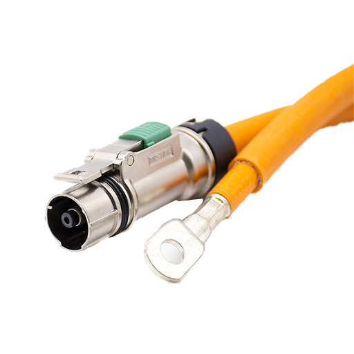
Renhotec EV Cable, crafted with top-notch conductive materials and meticulously engineered insulation, showcases outstanding impedance control and voltage-withstanding properties. Its design combines flexibility and durability to meet a wide array of installation needs. This cable is widely utilized in grid interconnections, large-scale industrial power supply systems, and high-voltage renewable energy projects, enabling smooth and efficient power transmission.
Renhotec, as a professional supplier, offers a comprehensive range of these Signal Transmission Connector products. Whether it is the high-reliability applications of the metal series or the wide adaptability of the plastic series in consumer electronic products, Renhotec can provide customers with high-quality options to meet the diverse requirements of signal transmission connections in different industries and scenarios.
Renhotec, active in electrical components, offers High Voltage DC Contactors in Epoxy Resin Sealing and Ceramic Sealing variants, with a 20A – 1000A current range. The Epoxy Resin Sealing one is cost-effective and protective. The Ceramic Sealing variant excels in thermal stability and insulation. They’re widely used in EV charging, renewable energy grid, and industrial high-voltage DC power distribution for reliable circuit control and current interruption, providing comprehensive solutions for multiple sectors.
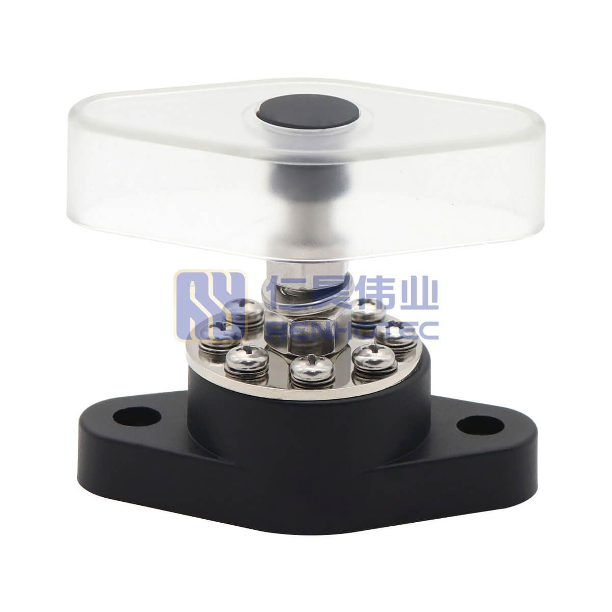
Battery Enclosure Wiring: Feed-Through Terminal Blocks vs. Cable Glands
When designing a battery enclosure or power distribution box, wiring entry is often treated as an afterthought. For low-power systems, a standard cable gland (often just a few dollars) and some internal busbars solve the issue perfectly.
But things change when it’s a high current application, e.g., 150A.
At 150A, you are dealing with 2 AWG or 1/0 AWG (roughly 35mm² to 50mm²) copper cables. These cables are thick, heavy, and stubborn to bend. Suddenly, the low-cost cable gland approach starts creating hidden costs on the assembly line and unexpected risks in the field. Let’s look at the physical realities of choosing between a feed-through terminal block and a cable gland in high-current systems, and see which one actually lowers your total cost of ownership.
Installation Inside the Box vs. Outside the Box
The main appeal of a cable gland is its simplicity: punch one hole in the panel, pass the cable through, and tighten. On a CAD drawing, it makes sense. On the shop floor, it’s a different story.
Once that rigid 50mm² cable is inside the enclosure, a technician has to bend it, align it, and bolt it to an internal busbar. Working with thick wire inside a cramped box is frustrating and it may take a rather long time. More importantly, limited hand space means it’s harder to apply the correct torque to the bolt. This directly leads to inconsistent connection quality.
A feed-through terminal block shifts this labor. Yes, it requires three holes on the panel (one main hole, two for mounting). However, it allows for a modular assembly process. The internal wiring can be bolted comfortably on the production line before the enclosure is fully assembled. When the equipment reaches the site, the field worker simply connects the external cable to the outside of the terminal block using a standard socket wrench. It turns a 15-minute internal struggle into a 2-minute external connection.
The Reality of “Inside the Box” Wiring
Look at the typical internal layouts in the photos above. While the wires shown here are for lower-current distribution, imagine trying to route a rigid, thumb-thick 50mm² (1/0 AWG) cable for a 150A system into a cramped space like this.
Field technicians would have to violently bend the heavy cable, align a massive ring terminal with the busbar, and attempt to apply maximum torque with almost no room for a wrench. This lack of operating space is exactly why internal field-terminations often fail. A feed-through terminal block solves this by moving that heavy-duty connection to the clean, open exterior of the panel.
Feed-Through Terminal Blocks vs. Cable Glands: Contact Resistance
A common argument for cable glands is that they allow a single, uncut cable to run directly to the internal busbar, which theoretically means lower resistance. Opponents of terminal blocks argue that cutting the cable and adding a connection point creates a bottleneck for heat.
This is a half-truth. Heat at the connection point isn’t caused by the presence of a terminal; it’s caused by poor contact area and insufficient clamping force.
Because space is restricted when terminating a gland-routed cable inside a box, technicians often fail to achieve a perfectly flat, high-torque mating surface. A high-quality 150A feed-through terminal block solves this through engineering. It uses a thick copper conductor to ensure maximum current flow. Furthermore, the M8 external threads allow technicians to easily apply full, standardized torque, ensuring a solid face-to-face connection with the ring terminal.
Even under continuous load, a well-torqued terminal block maintains stable temperatures. To handle normal operational heat, industrial-grade terminal housings use UL94-V0 rated flame-retardant plastics designed to operate safely between -40°C and +125°C. They won’t soften or degrade over time, unlike some basic rubber grommets under thermal stress.
Metal Cable Glands
Vibration Tolerance: Flange Mount vs. Compression Seal
Vibration is the enemy of any electrical connection, especially in energy storage systems or recreational vehicles.
Cable glands rely on rubber deformation. As you tighten the gland, a rubber seal compresses around the cable jacket. While this provides a great static IP67 seal, it struggles dynamically. If that thick 150A cable is pulled or shaken constantly, the stress transfers directly to the rubber seal, eventually causing fatigue, loosening, and moisture ingress.
A 2-hole flange terminal block uses mechanical isolation. The terminal body is bolted directly to the metal panel. Any external pulling or vibration from the heavy cable is absorbed entirely by the flange and the panel itself. The internal O-ring, which provides the IP67 waterproofing, sits completely protected from these mechanical stresses. It stays sealed because it never takes the load.
(Note: High-voltage systems must always be powered down before any maintenance or disconnection.)
When an inverter module or battery pack needs to be swapped, downtime and safety are the top priorities.
With a cable gland setup, disconnecting the main power means opening the main equipment enclosure. This exposes the maintenance worker to internal high-voltage busbars and sensitive components.
Terminal blocks keep the danger enclosed. Technicians can unbolt the main cables from the outside without ever opening the box. High-quality terminals also feature IP2X (touch-proof) designs, preventing accidental finger contact with the conductive core even when cables are removed. Additionally, molded red and black color-coding (Poka-yoke design) ensures that when it’s time to reconnect, the risk of reversed polarity is virtually eliminated.
How to Choose?
A simple cable gland might save you a few cents on your Bill of Materials (BOM). However, in a high current system, those savings are quickly wiped out by difficult factory assembly, inconsistent torque, and higher maintenance risks. For high-current, dynamic environments, investing in a standardized feed-through terminal block is the engineered choice for long-term reliability.
Selection Criteria
Cable Gland (with Internal Busbar)
Feed-Through Terminal Block (2-Hole Flange)
Current & Cable Size
Best for low current (<50A) and flexible, thin wires.
Engineered for high current (100A+) and rigid, thick cables (35-50mm²).
Assembly & Labor
High labor: Requires bending thick cables and torquing bolts inside a cramped enclosure.
Modular & fast: Allows pre-assembly. Field connections are made externally in minutes.
Thermal Stability
Overheating risk: Prone to high resistance if limited internal space prevents proper bolt torque.
Highly stable: External M8 threads allow full, standardized torque for maximum contact area.
Vibration & Sealing
Static IP67: Rubber seals degrade and loosen under dynamic cable pulling or heavy vibration.
Dynamic IP67: Mechanical stress is absorbed by the mounting flange, fully protecting the internal O-ring.
Maintenance & Safety
Hazardous: Requires opening the main enclosure, exposing technicians to live high-voltage busbars.
Safe & isolated: External disconnect without opening the box. Features IP2X touch-proof design.
Total Cost of Ownership
Lowest BOM cost, but hidden costs in assembly time and field failures are extremely high.
Higher initial part cost, but significantly lowers factory assembly time and eliminates warranty risks.
They are standardized components. Our 150A 2-hole flange terminal blocks follow industry-standard panel cutout dimensions and thread pitches. They are fully compatible and interchangeable with mainstream market designs, meaning procurement teams won’t face vendor lock-in or supply chain bottlenecks.
No. A proper terminal block comes with a custom-fitted sealing gasket (or O-ring) at the base. As long as the flange is tightened to the panel with the recommended torque, it achieves IP67 protection natively. Skipping the messy silicone step simplifies your SOP.
Our terminal housings are manufactured with UL94-V0 flame-retardant plastics and are designed to meet IP2X touch-proof standards, aligning with strict European and North American electrical safety regulations.

 Deutsch
 Русский