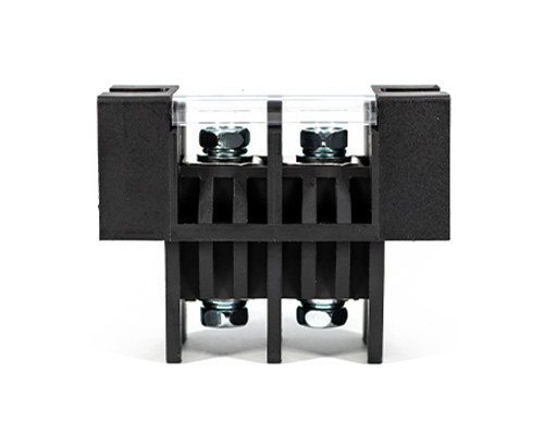
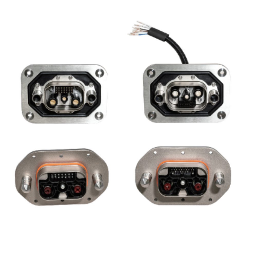
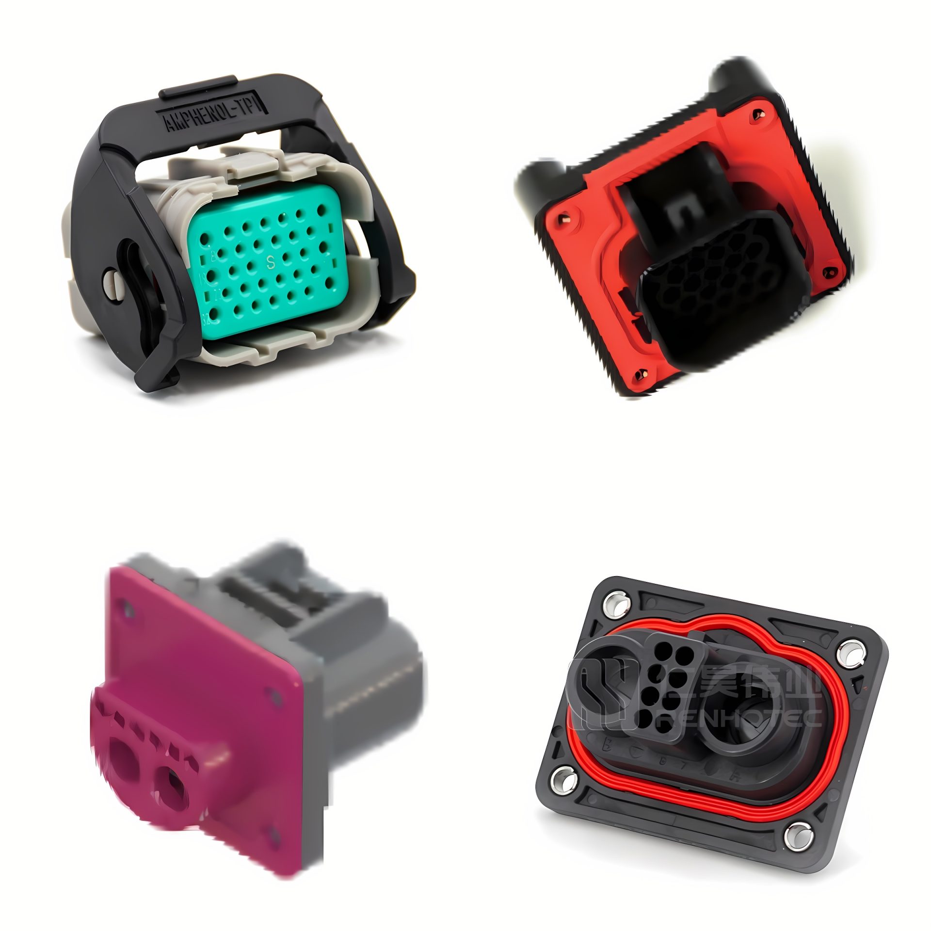
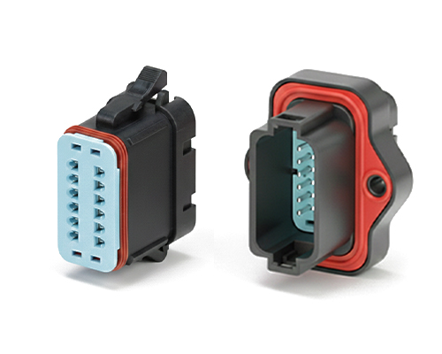
The Rectangular Connector is widely used in aerospace, medical instruments, consumer electronics (such as computers, TVs, game consoles, etc.), industrial control equipment, communication equipment, and automotive electronics. With its reliable connection performance, diverse specifications, and relatively convenient plug-in and unplug operations, it has become an indispensable component in various electronic and electrical applications.
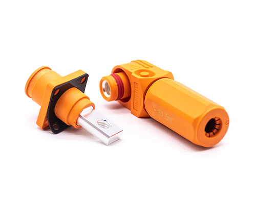
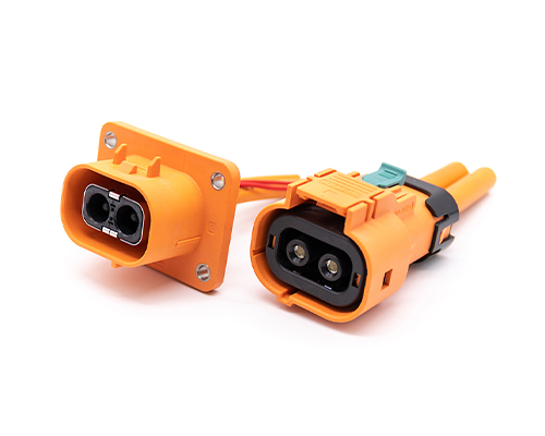
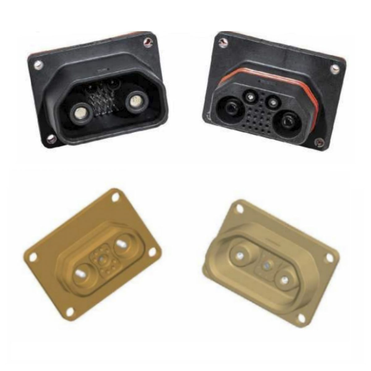
High Voltage Connectors are widely used in EV power systems, renewable energy installations, and industrial high-voltage circuits. Renhotec’s series drives the building of efficient, safe, and sustainable electrical ecosystems, meeting current technological demands.
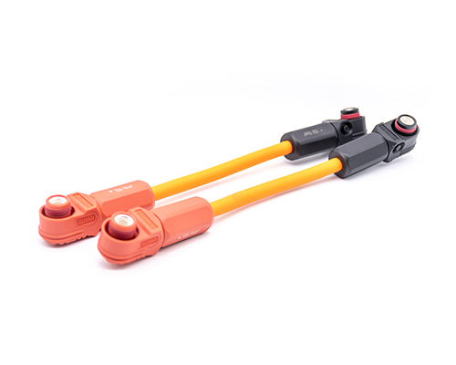
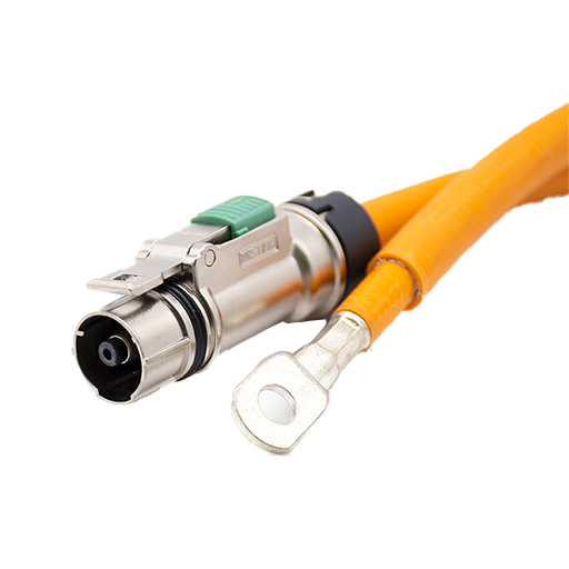
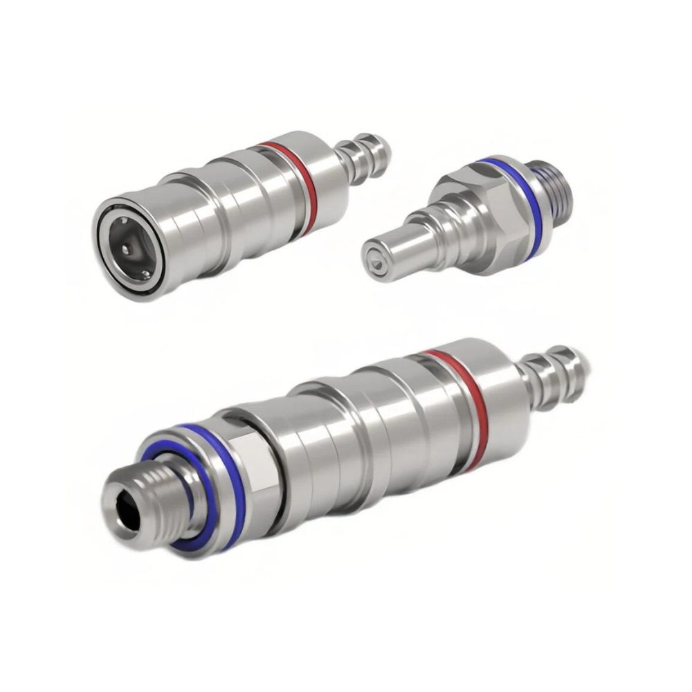
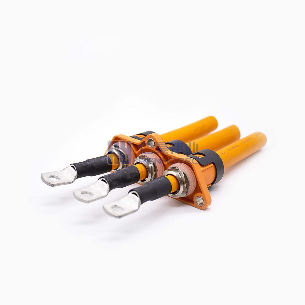
Renhotec EV Cable, crafted with top-notch conductive materials and meticulously engineered insulation, showcases outstanding impedance control and voltage-withstanding properties. Its design combines flexibility and durability to meet a wide array of installation needs. This cable is widely utilized in grid interconnections, large-scale industrial power supply systems, and high-voltage renewable energy projects, enabling smooth and efficient power transmission.
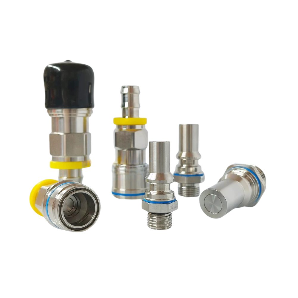
Renhotec, as a professional supplier, offers a comprehensive range of these Signal Transmission Connector products. Whether it is the high-reliability applications of the metal series or the wide adaptability of the plastic series in consumer electronic products, Renhotec can provide customers with high-quality options to meet the diverse requirements of signal transmission connections in different industries and scenarios.
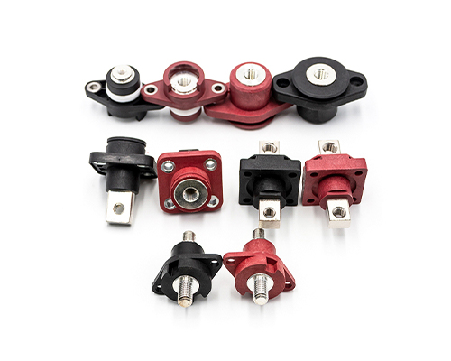
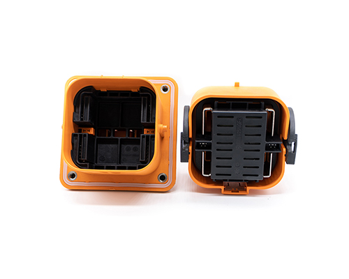
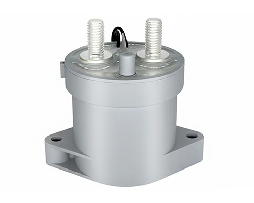
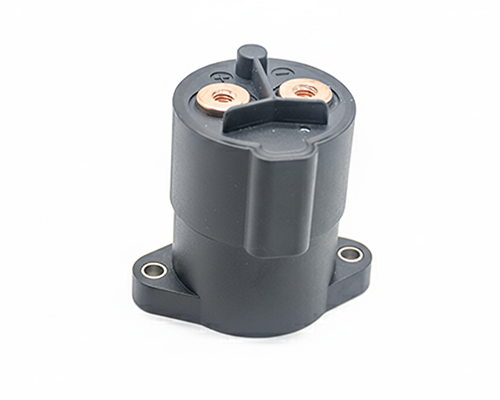
Renhotec, active in electrical components, offers High Voltage DC Contactors in Epoxy Resin Sealing and Ceramic Sealing variants, with a 20A – 1000A current range. The Epoxy Resin Sealing one is cost-effective and protective. The Ceramic Sealing variant excels in thermal stability and insulation. They’re widely used in EV charging, renewable energy grid, and industrial high-voltage DC power distribution for reliable circuit control and current interruption, providing comprehensive solutions for multiple sectors.
Micro-D connectors are developed for applications where space, weight, and reliability are critical. When board space is at an absolute premium and weight reduction is critical, standard D-Sub connectors simply take up too much room. This is where the Micro-D connector comes in.
A Micro-D connector is a miniaturized rectangular connector. The defining characteristic of a true Micro-D is its 1.27mm contact pitch – exactly half the spacing of a standard D-Sub. This high-density design allows engineers to pack a massive number of signal channels into a fraction of the physical footprint. Typically housed in a rugged metal or high-performance plastic shell, these connectors are engineered tomaintain secure, low-resistance electrical connections even when subjected to extreme physical stress.
Micro-D connectors are widly manufactured based on Military Detail Specification “MIL-DTL-83513” which assigns unified structures and sizes. As the “MIL-DTL-83513” has become a universal solution in the market, micro-d connectors are also called M83513 connectors. The most common alternative to micro-d connector is the J30J series connector.
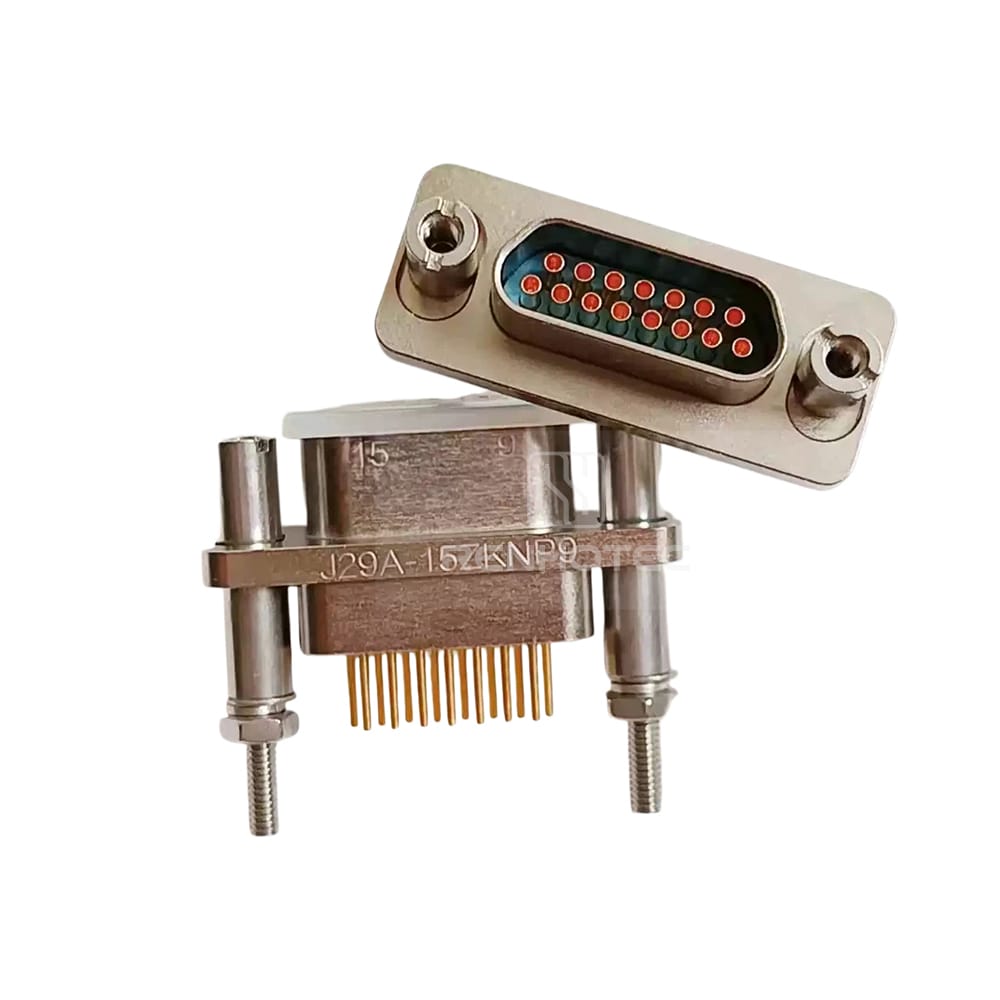
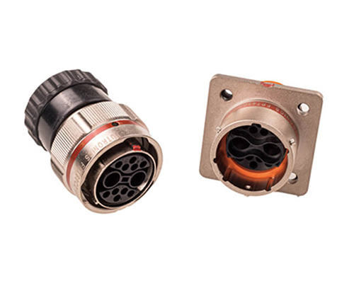
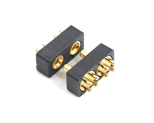
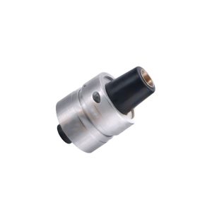
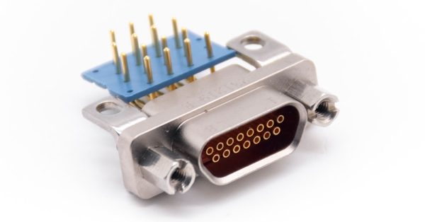
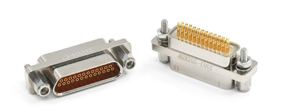
J30J-15ZKW Micro-D Connector
Key Application Scenarios of Micro-D Connectors
Micro-D connectors are not standard commercial components; they are built for environments where failure is not an option. They are widly used in industries that demand a high degree of ruggedness combined with strict size, weight, and power (SWaP) requirements:
Aerospace & Aviation: Used in avionics, UAV flight control systems, and satellite communications, e.g., flight black boxes, navigation gyroscope modules, and internal wiring harness connections in satellite payload panels, where payload weight must be minimized without sacrificing signal integrity.
Defense & Military Electronics: According to our client needs, they’re integrated into radar systems, ruggedized displays, and secure communication devices that must withstand high impact and constant vibration. Common installation locations include the signal processing board of a phased array radar, the rear panel I/O ports of a tactical ruggedized computer terminal, and board-to-board bridging inside an encrypted handheld radio.
Medical Equipment: Essential for MRI machines, portable diagnostic devices, and surgical robots that require high-density data transfer in tight enclosures. Engineers typically designate it for sensor connections to MRI patient examination tables, high-density probe interfaces for portable ultrasound equipment, and multi-axis joint controllers for surgical robotic arms.
Deep-Sea & Industrial: Deployed in downhole drilling tools and underwater ROVs, often utilizing hermetically sealed variations to withstand extreme pressure and prevent gas or moisture ingress. In these fields, hermetically sealed Micro-D connectors are used as bulkhead penetrators (watertight penetration devices) on ROV pressure hulls, and as probe interfaces for logging-while-drilling (LWD) tools.
How to Choose Micro-D Connectors for Your Application
Step 1: Define the Application Environment
The first step in selecting a Micro-D connector is to clearly define the application environment. Consider factors such as operating temperature, vibration level, shock resistance, and whether the application is in aerospace, military, or industrial equipment. These conditions determine whether a standard Micro-D or a ruggedized/sealed version is required.
Step 2: Determine the Connection Type
How will the connector integrate into your system? The choice of termination directly impacts manufacturing and reliability:
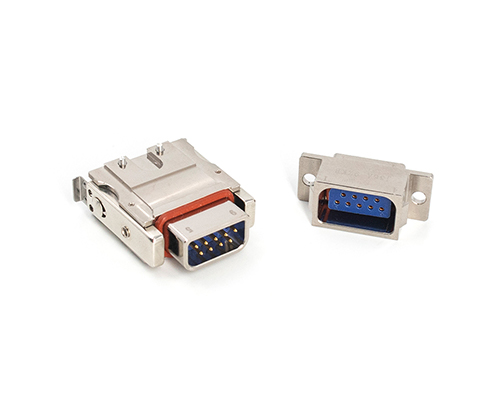
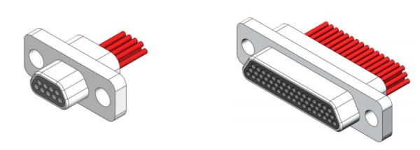
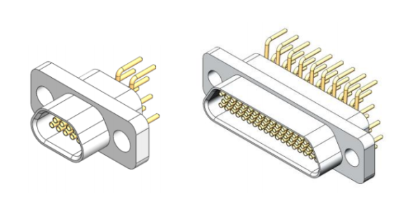
Crimp Type: Ideal for discrete wire harnesses, offering excellent mechanical strength and resistance to vibration.
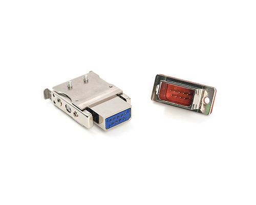
Solder Cup: Used for manual wire termination, often preferred for prototyping or low-volume, highly customized cable assemblies.
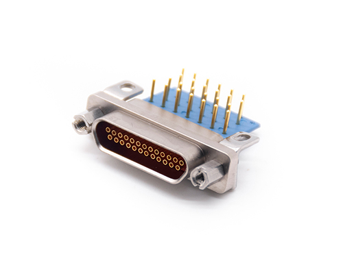
PCB Type (Straight or Right-Angle): Designed for direct board mounting. Engineers must pay close attention to the grid pitch (e.g., 2.54 x 2.54mm or a tighter 1.27 x 2.54mm) to ensure proper mating with the PCB layout.
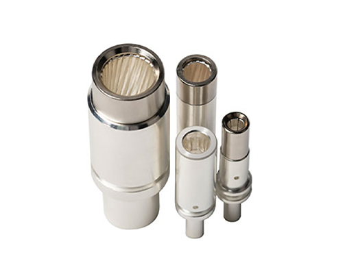
Crimp Type PlugSolder Type Plug and ReceptacleStraight PCB Type Receptacle
Step 3: Select the Number of Contacts (Pin Count)
Micro-D connectors generally offer standard layouts ranging from 9 to 100 contacts. The goal is to match your signal requirements while considering the maximum allowable panel cutout or board footprint. Generally, 9-pin micro-d connectors handle basic signal transmission in space-constrained devices, 15-pin configurations support balanced multi-channel data in control units, and 100-pin layouts are reserved for high-density signal routing in complex avionics.
The dimensions of a micro-D connector vary primarily based on its pin count and row configuration. For products compliant with the MIL-DTL-83513 standard, the key spatial parameters typically fall within the following ranges:
Mounting Hole Spacing: Approximately 14.4 mm (for 9-pin) to 45.7 mm (for 100-pin).
Profile/Width: Approximately 7.5 mm to 11.0 mm.
The table below details the specific mounting hole spacing values based on MIL-DTL-83513 specifications.
Layout
Row Configuration
Mounting Hole Spacing(inches)
Mounting Hole Spacing(mm)
9
2
0.565
14.4
15
2
0.715
18.2
21
2
0.865
22.0
25
2
0.965
24.5
31
2
1.115
28.3
37
2
1.265
32.1
51
3
1.215
30.9
100
4
1.800
45.7
Step 4: Choose the Connector Layout and Mounting Style
At this stage, you need to select the mechanical structure of the connector. This includes plug or receptacle type, straight or right-angle orientation, and mounting method such as panel mount or PCB mount. These choices must align with your mechanical design constraints.
Step 5: Verify Electrical Requirements
Ensure that the connector meets your electrical specifications, including current rating, voltage rating, contact resistance, and insulation performance. Standard Micro-D connectors typically support around 3A per contact, but this must be validated against your application.
Step 6: Evaluate Environmental and Reliability Requirements
For demanding applications, additional factors such as sealing, EMI shielding, corrosion resistance, and lifecycle durability must be considered. If the connector will be used in harsh environments, selecting a high-reliability version is essential.
Step 7: Select Termination Style and Accessories
Finally, determine the termination type and any required accessories. Options may include solder cup, crimp contacts, or pre-wired assemblies. Additional components such as backshells, strain reliefs, and shielding accessories may also be necessary for optimal performance.
Micro-D Connector Equivalents
Ordering standard M83513 connectors from leading global manufacturers often results in extended lead times (frequently exceeding 16 weeks) and high BOM costs. This has driven engineers to seek high-quality, drop-in equivalents that maintain the same form, fit, and function.
For many global aerospace and industrial projects, the J30J connector series has emerged as the industry-standard alternative, offering a robust balance between technical compliance and supply chain efficiency.
Performance and Intermateability: Widely recognized under the GJB 2446A standard (the equivalent to MIL-DTL-83513), the J30J series fully aligns with the design logic of the Micro-D family. Featuring a metal shell for superior EMI/RFI shielding and high-reliability twist pin contacts, it ensures stable signal transmission in high-vibration environments. Because it shares the exact same 1.27mm pitch and contact arrangement, the J30J guarantees 100% mating compatibility with existing MIL-spec Micro-D hardware.
Panel Cutout Considerations: While the mating interfaces are completely identical, there are fractional millimeter differences in the outer shell dimensions due to metric versus imperial manufacturing standards. This minor variance only becomes relevant when designing panel cutouts. If you are replacing legacy equipment, we recommend verifying the exact mounting hole spacing to ensure compatibility with your existing panels.
The table below compares the mounting hole spacing between the MIL-DTL-83513 standard and the J30J series to help you accurately update your mechanical drawings:
Layout
Row Configuration
MIL-DTL-83513 Mounting Hole Spacing(mm)
J30J Series Mounting Hole Spacing(mm)
9
2
14.4
14.3
15
2
18.2
18.2
21
2
22.0
22.0
25
2
24.5
24.5
31
2
28.3
28.3
37
2
32.1
32.2
51
3
30.9
30.86
66
3
N/A
37.3
69
3
N/A
38.5
74
4
N/A
33.5
100
4
45.7
45.7
Note: 66, 69, and 74-pin layouts are exclusive extensions of the J30J series designed for specific high-density requirements and are not defined in standard MIL-DTL-83513 specifications.
Supply Chain Advantage: Backed by mature manufacturing capabilities and a robust supply chain, the lead time for J30J connectors is typically around 4 weeks—significantly optimizing your project timeline without compromising on military-grade reliability.
How to Select and Specify a J30J Connector
The process of selecting a J30J connector is almost the same as that of selecting a Micro-D connector. On the belowing is a form of our J30J series products part numbering system. Most products cover 9 – 100 pins, some modified products cover 9 – 37 or 9 – 66 pins.
K, L — Free-end Locking AssemblyP, V — Fixed-end Locking Assembly
X
Modification Code
A — Shielding Sleeve (Crimp only)C — Vertical Wire Exit (Crimp only)D — Anti-rotation Structure (Fixed-end only)AD — Combination of A and DJ — 1.27mm × 2.54mm PCB Grid SpacingQ, Q8 — Widened Flange
E.g., J30J-15ZPK, is a 15 pin receptacle with socket and fixed-end locking assembly.
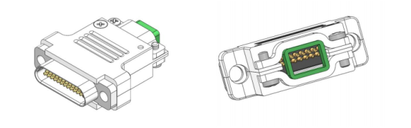
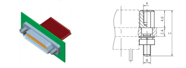
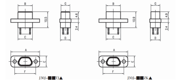
The dimensional drawings for J30J micro-d connectors are shown below.
Fixed-end Locking Assembly ExampleSize of J30J Crimp Basic Types Connectors
Choosing the right D-sub Micro-D connector is a balance of density, reliability, and availability. By understanding the universal selection logic and leveraging the versatile J30J series, engineers can achieve high-performance connectivity that meets the most demanding standards. Whether your project requires a standard crimp connection or a specialized glass-to-metal hermetic seal, the J30J provides a proven, cost-effective, and technically equivalent solution to traditional M83513 connectors.