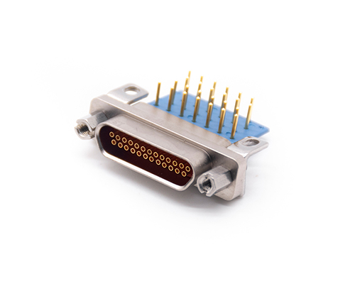
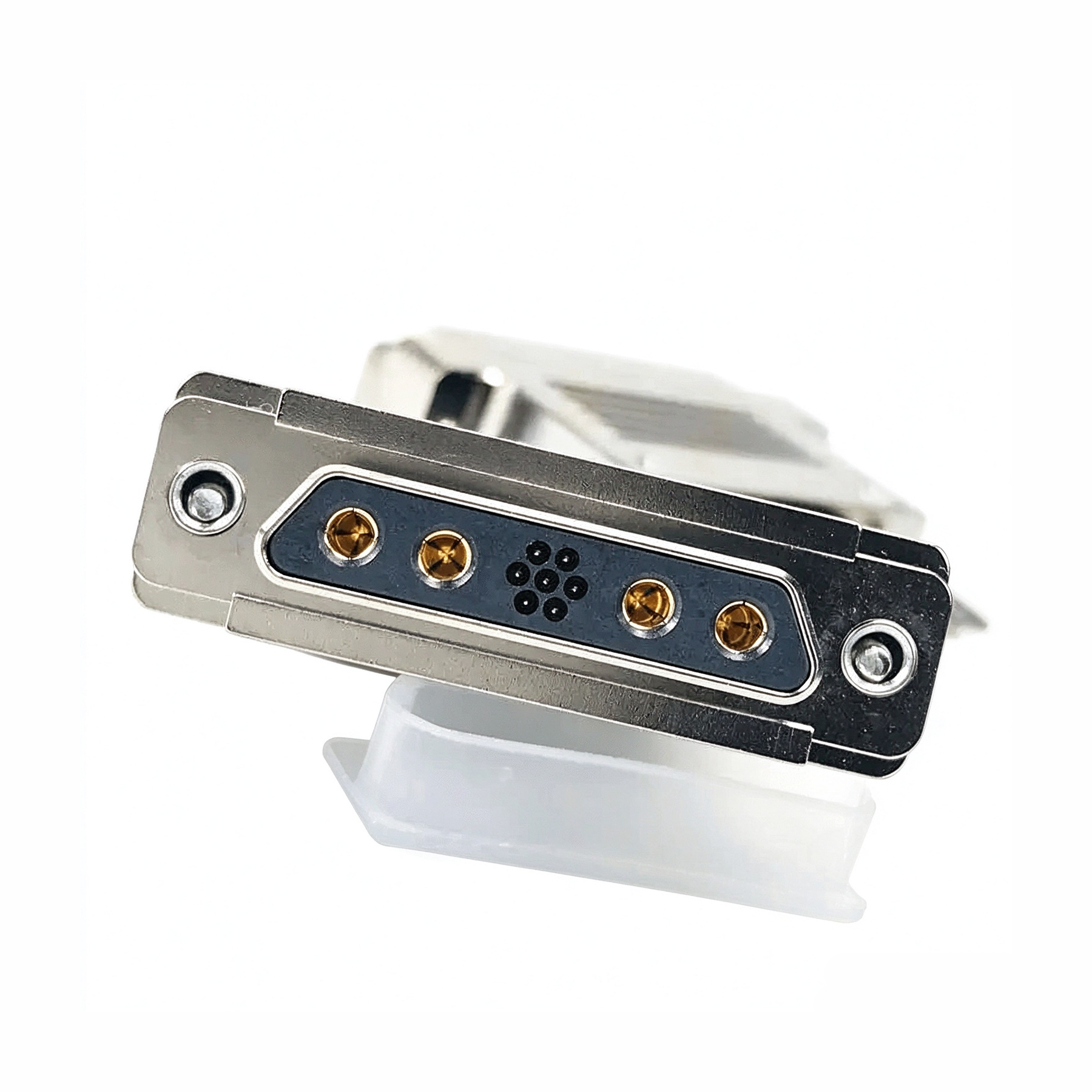
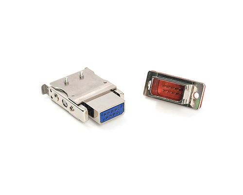
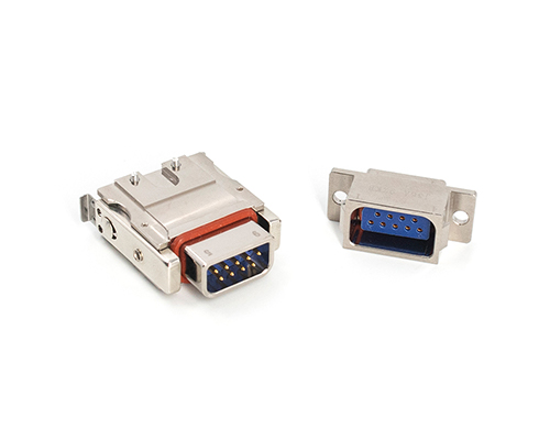
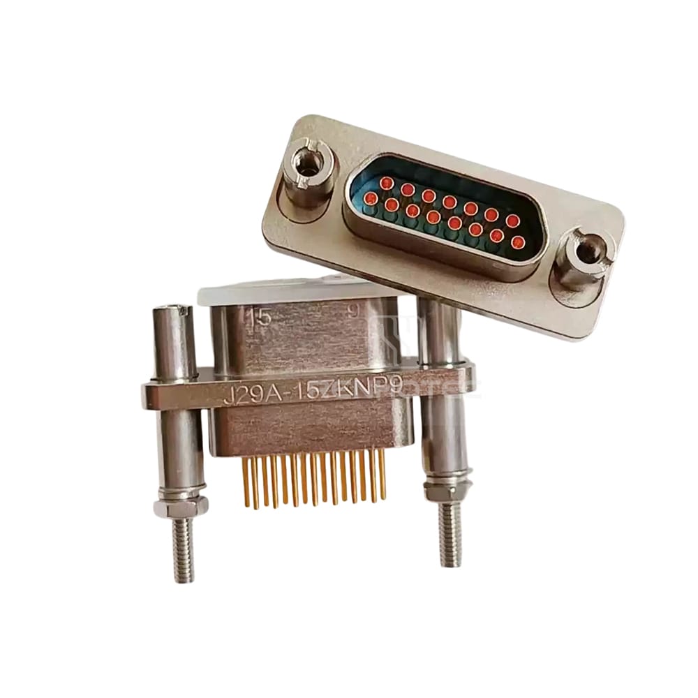
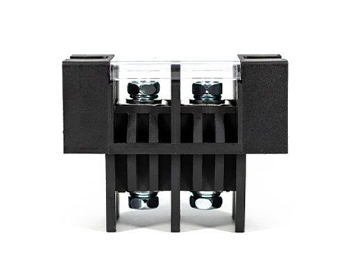
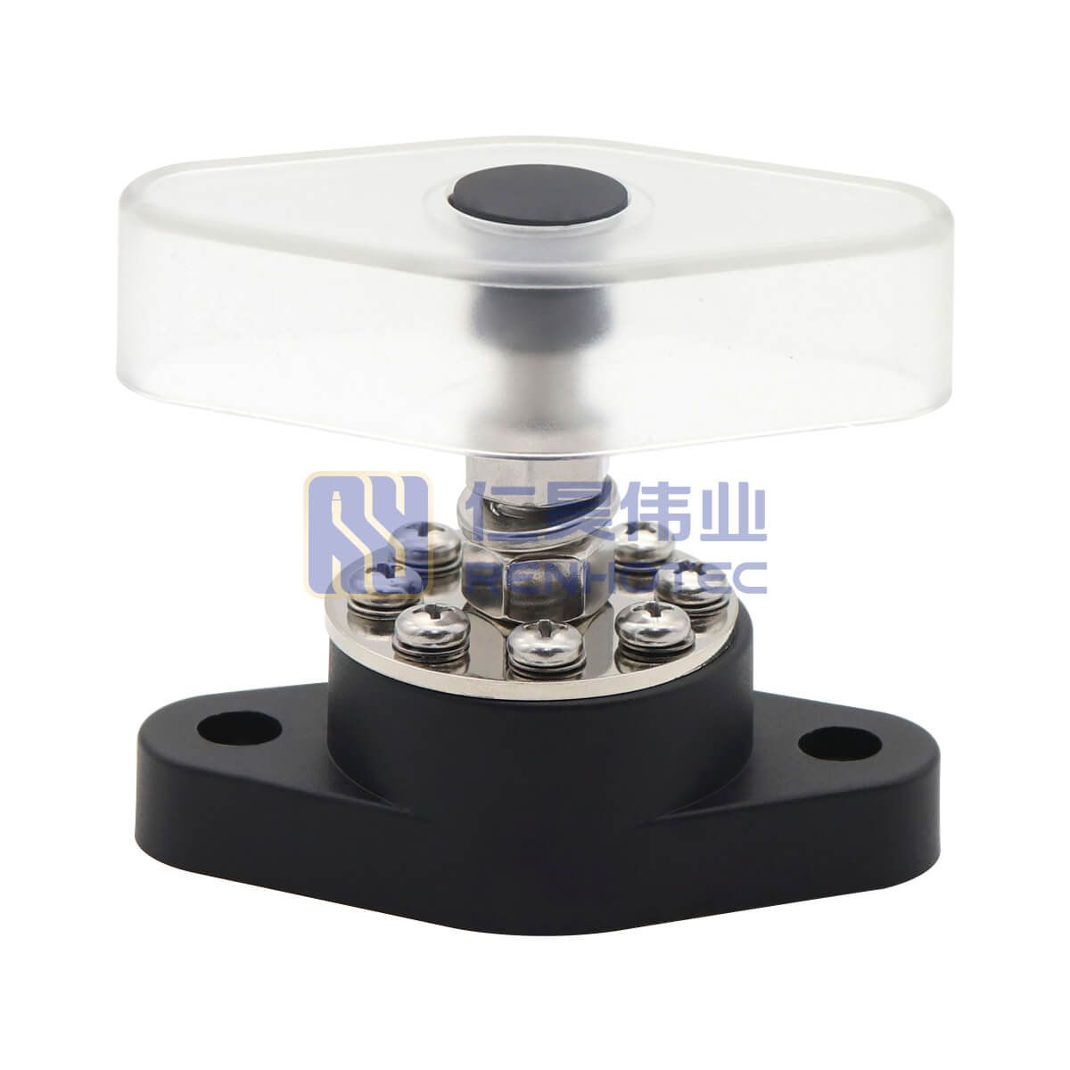
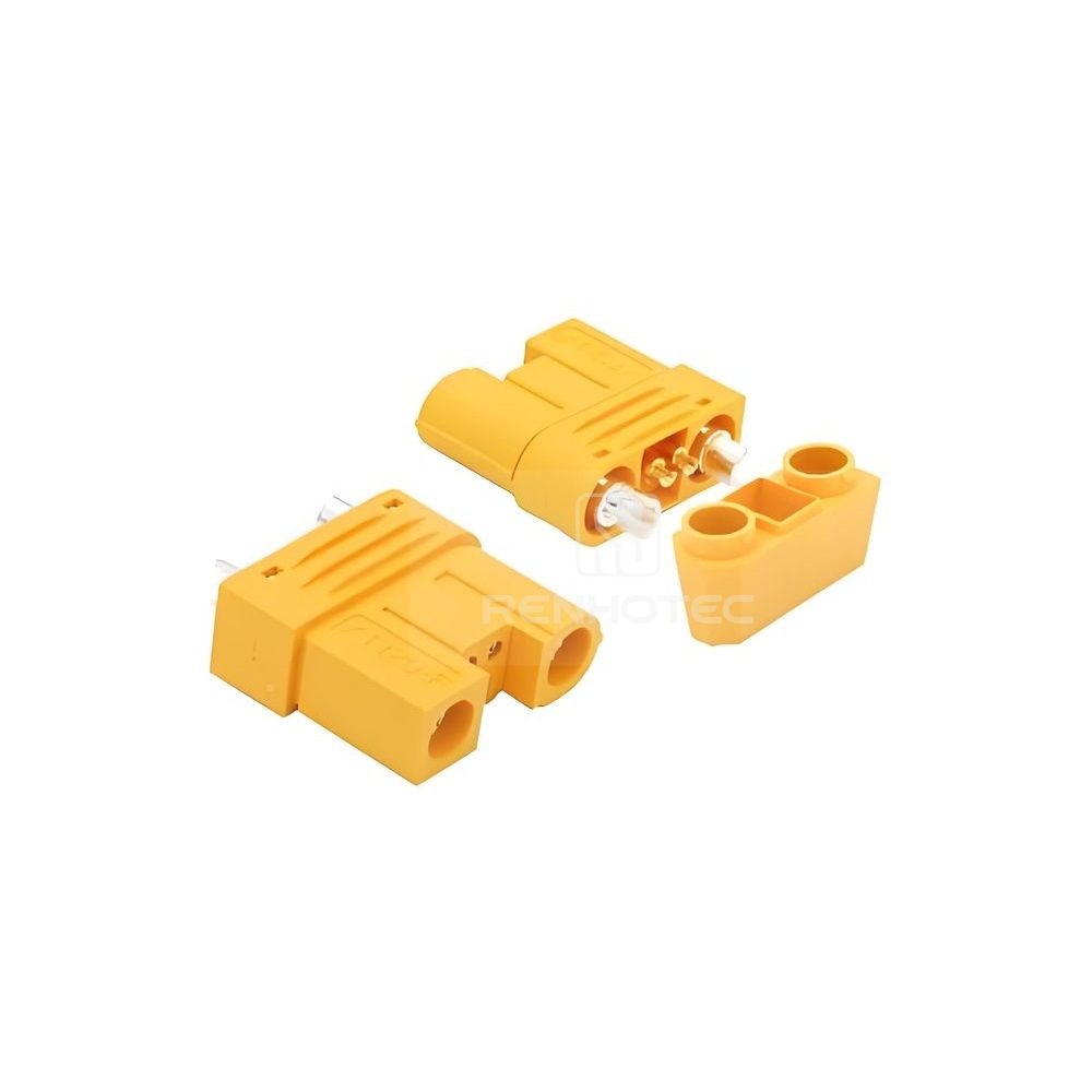
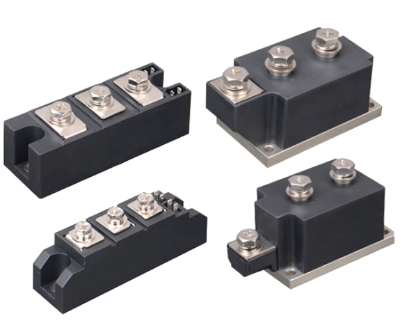
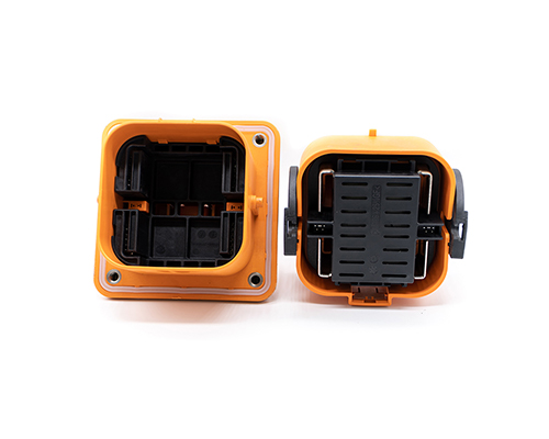
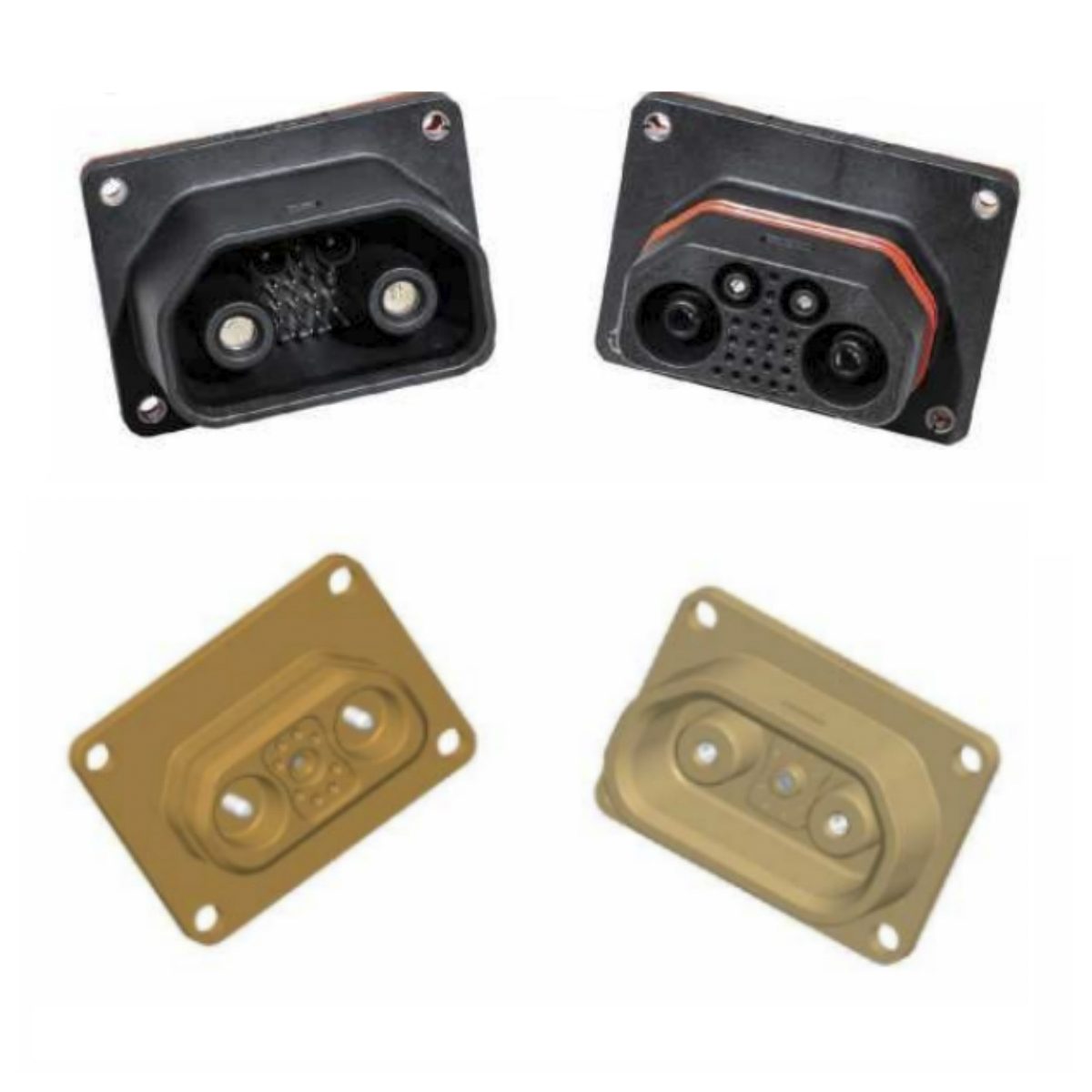
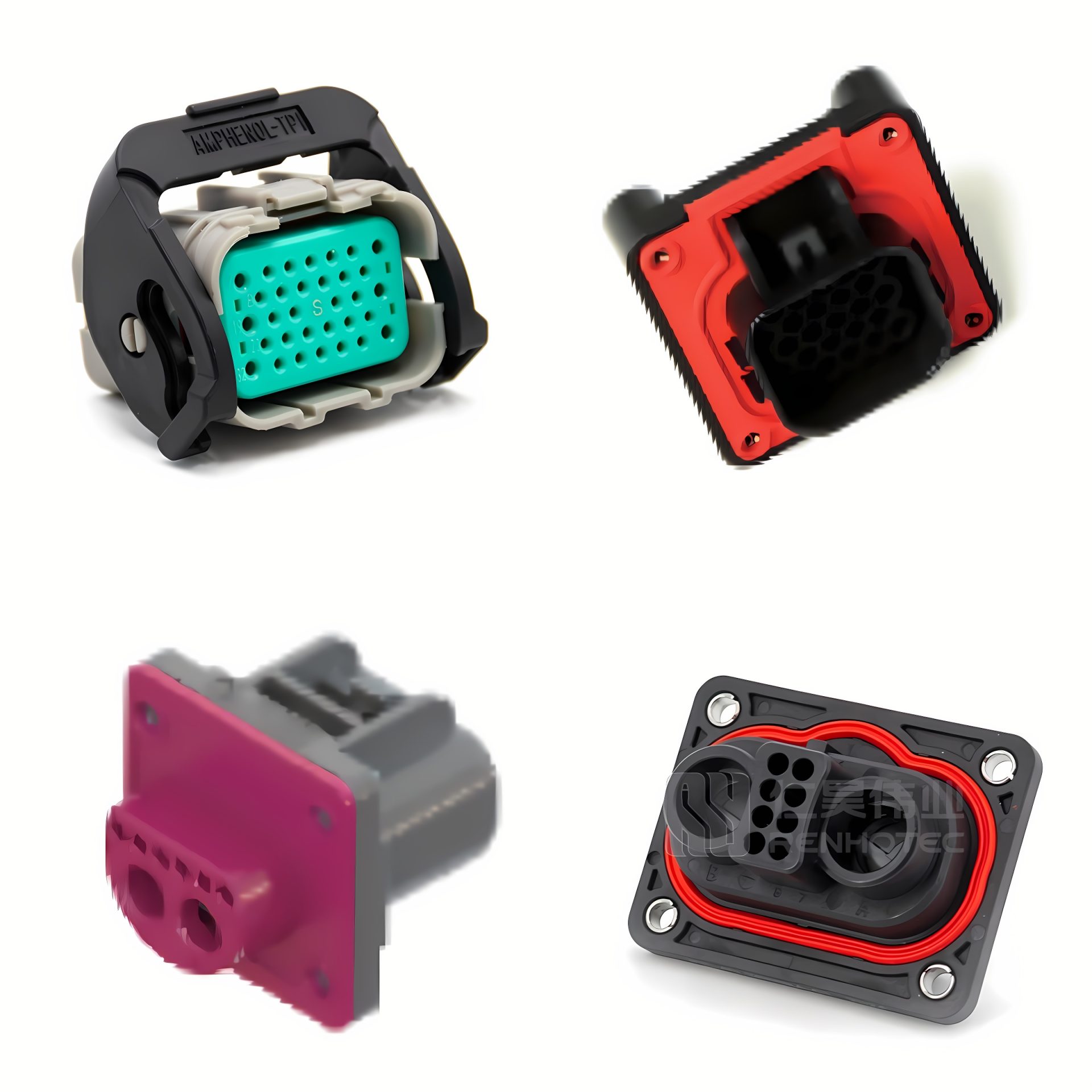
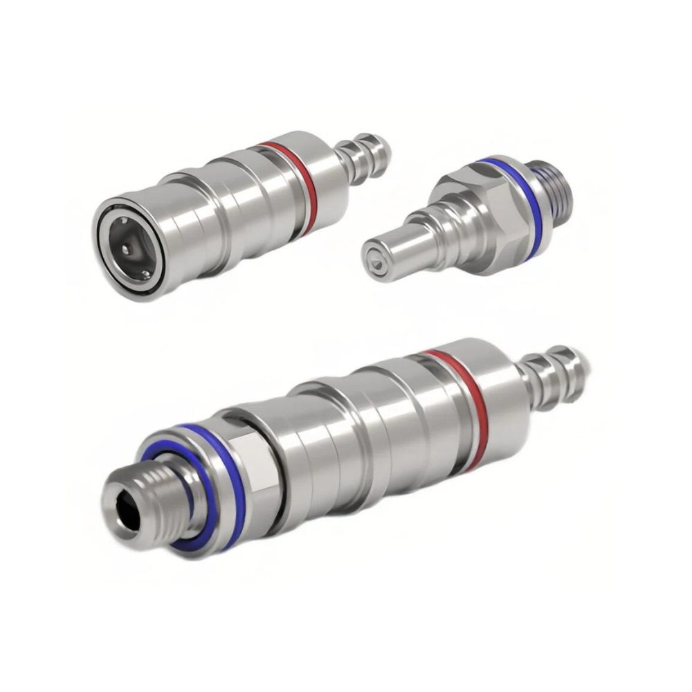
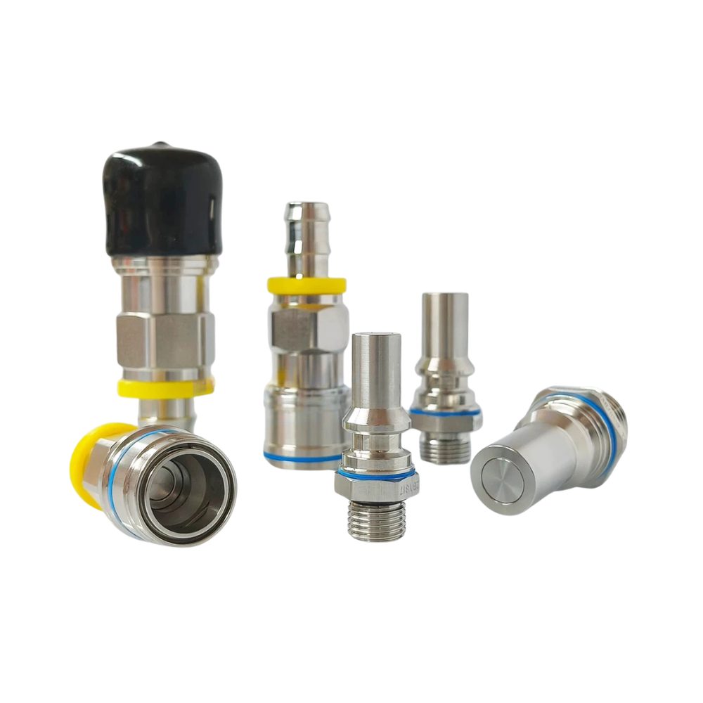
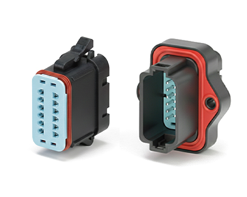
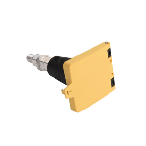
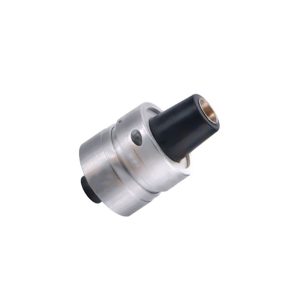
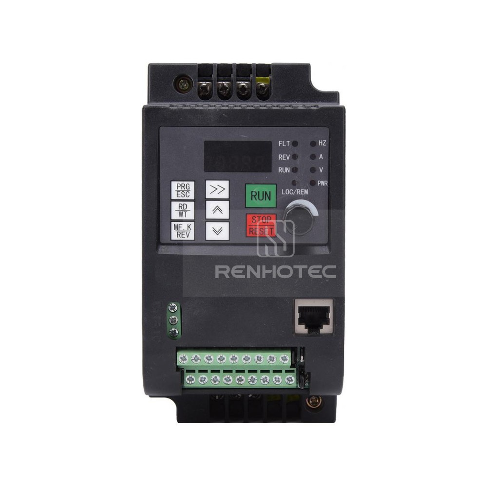
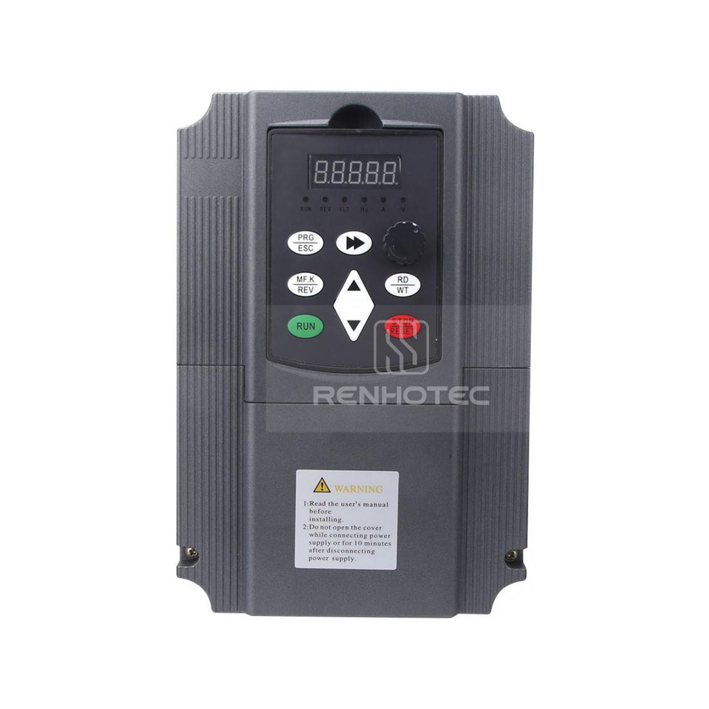
The Rectangular Connector is widely used in aerospace, medical instruments, consumer electronics (such as computers, TVs, game consoles, etc.), industrial control equipment, communication equipment, and automotive electronics. With its reliable connection performance, diverse specifications, and relatively convenient plug-in and unplug operations, it has become an indispensable component in various electronic and electrical applications.
J30J General Connectors and Cable Assemblies
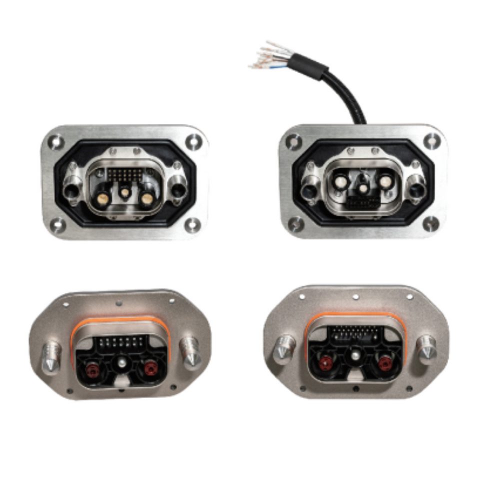
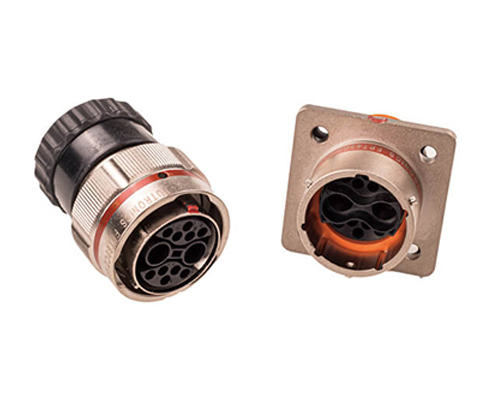
J30J Mixed Current (Hybrid) Connectors and Cable Assemblies
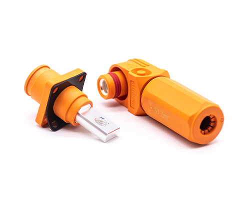
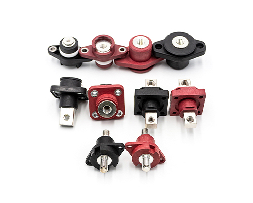
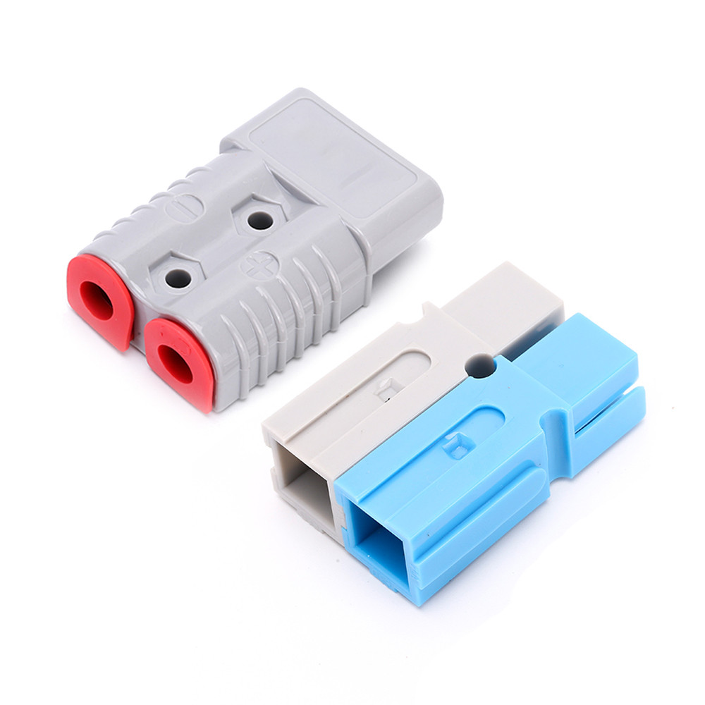
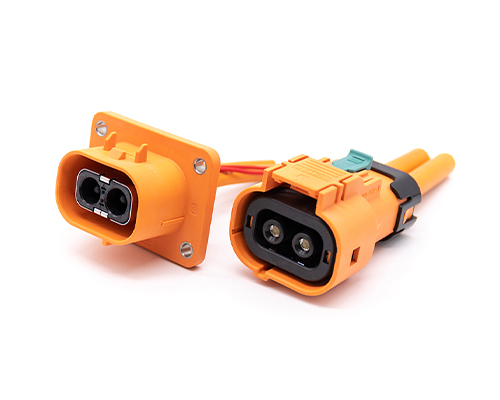
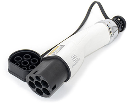
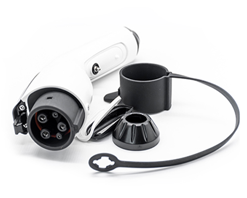
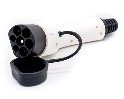
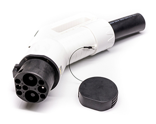
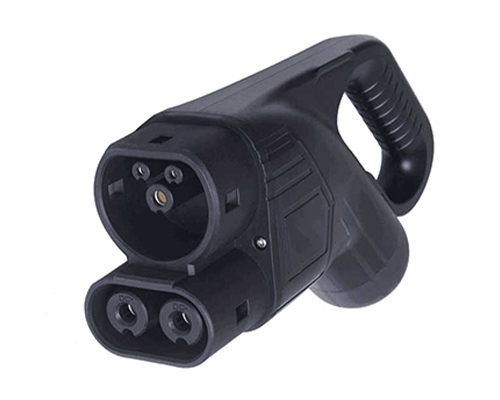
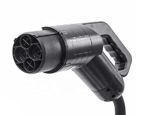
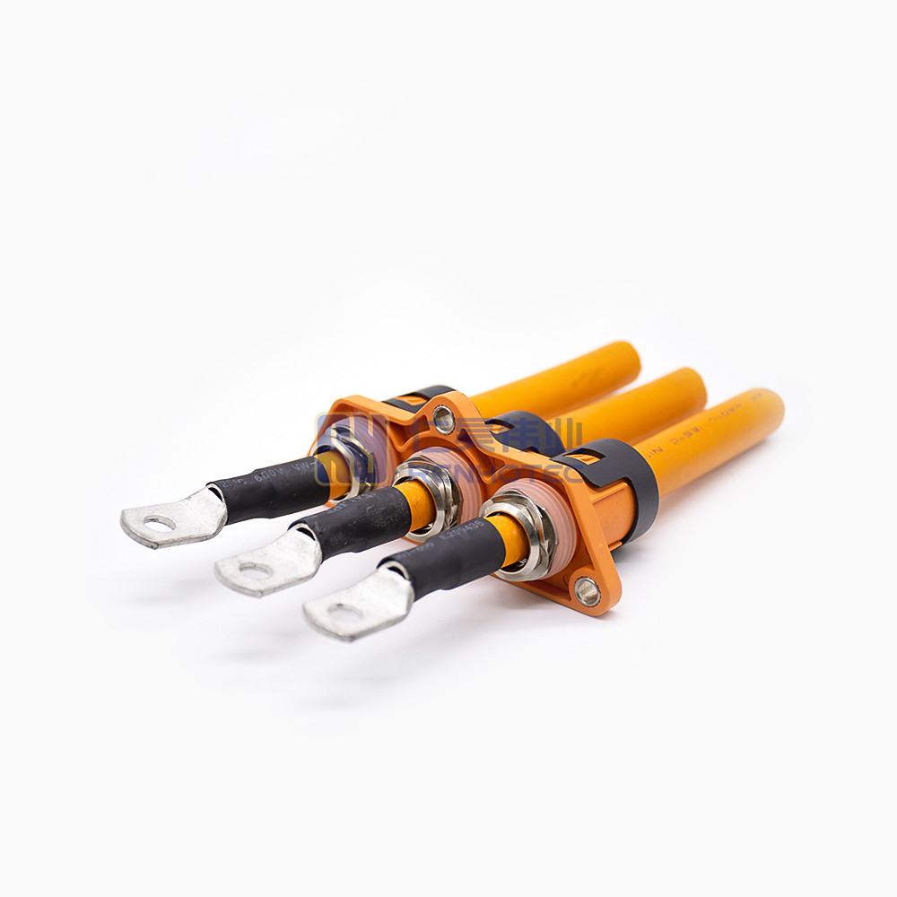
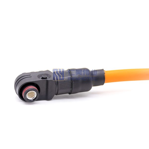
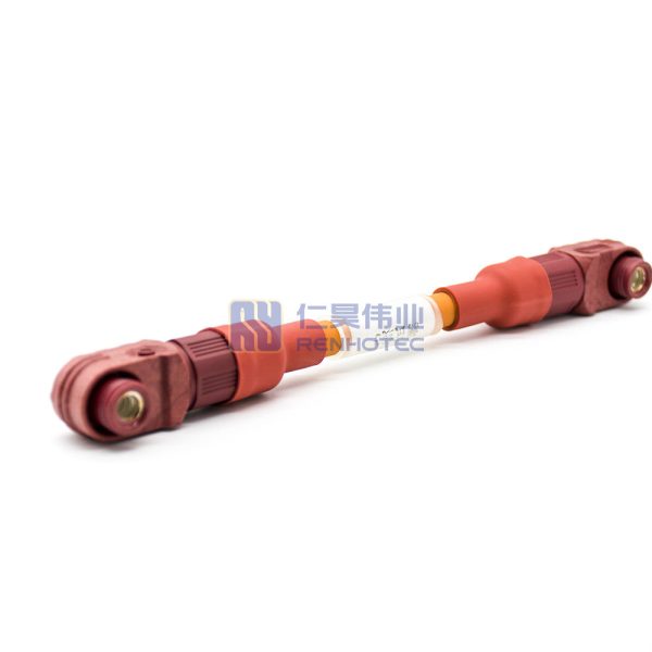
High Voltage Connectors are widely used in EV power systems, renewable energy installations, and industrial high-voltage circuits. Renhotec’s series drives the building of efficient, safe, and sustainable electrical ecosystems, meeting current technological demands.
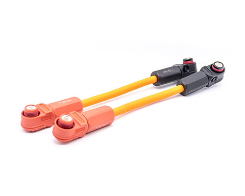
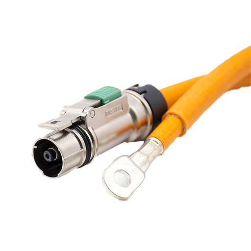
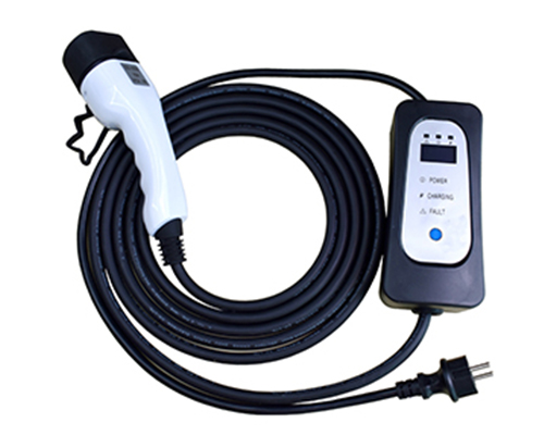
Renhotec EV Cable, crafted with top-notch conductive materials and meticulously engineered insulation, showcases outstanding impedance control and voltage-withstanding properties. Its design combines flexibility and durability to meet a wide array of installation needs. This cable is widely utilized in grid interconnections, large-scale industrial power supply systems, and high-voltage renewable energy projects, enabling smooth and efficient power transmission.
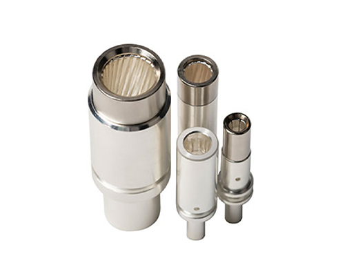
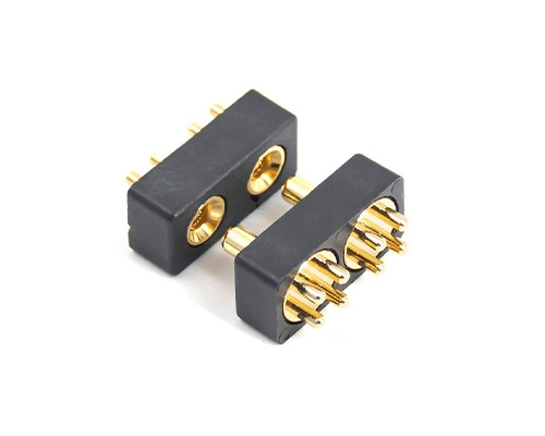
Renhotec, as a professional supplier, offers a comprehensive range of these Signal Transmission Connector products. Whether it is the high-reliability applications of the metal series or the wide adaptability of the plastic series in consumer electronic products, Renhotec can provide customers with high-quality options to meet the diverse requirements of signal transmission connections in different industries and scenarios.
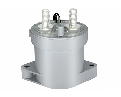
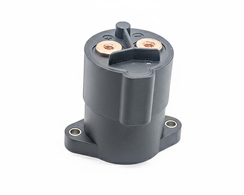
Renhotec, active in electrical components, offers High Voltage DC Contactors in Epoxy Resin Sealing and Ceramic Sealing variants, with a 20A – 1000A current range. The Epoxy Resin Sealing one is cost-effective and protective. The Ceramic Sealing variant excels in thermal stability and insulation. They’re widely used in EV charging, renewable energy grid, and industrial high-voltage DC power distribution for reliable circuit control and current interruption, providing comprehensive solutions for multiple sectors.
Battery Storage Cable Assemblies: What to Specify Before You Order
Battery storage · Cable assemblies
Specify the connections, cable length and operating conditions before comparing prices or ordering samples.
“A red battery cable, 200 A, 300 mm long” leaves room for very different quotations. Does the cable need two connectors, a connector and a lug, or one unfinished end? Where does the 300 mm measurement start and finish?
For a battery rack or energy storage cabinet, start with the connection at each end and the route between them. List DC power cables separately from battery-management-system signal harnesses, which need their own wiring diagrams and pin assignments.
Label the equipment connections A and B on your sketch, with the mating part number or terminal drawing for each.
Connector to connector
Each cable connector must match the specified equipment-side part, including its keying. Your drawing should also show the cable exit direction at both ends.
Connector to bolted terminal
Along with the connector part number, specify the lug’s conductor size, fastening-hole size and orientation. A busbar or terminal drawing lets the supplier check the lug against the connection surface and available space.
Connector with a free cable end
State whether the free end should be unstripped or stripped to a defined length, and who will terminate and inspect it. If the supplier is to fit a terminal before delivery, include that terminal’s specification in the order.
The 6 mm and 8 mm entries describe terminal size; 25 mm² and 50 mm² describe conductor cross-sectional area. “6 mm cable” is ambiguous. Use both values in your enquiry: “6 mm terminal, 25 mm² conductor.”
Define length and installed orientation
Mark both measurement points on the drawing, with a tolerance. Finished assembly length, exposed cable length and cut-wire length describe different dimensions, so name the one you need.
Length referenceStraight-layout example
A Connector interface centerB Lug-hole centerL ± t Specified length and tolerance
For a routed assembly, agree the measurement path as well as the two end references.
For a connector-to-lug assembly, the drawing can use the connector interface center or a specified reference face at one end, and the lug-hole center at the other. A connector-to-connector assembly needs a reference at each connector. Agree whether the dimension follows the cable centerline or is measured in another defined condition.
Show where the cable turns, where it is supported and how the connector can be released for service. Use the cable’s specified minimum bend radius and check the space needed for the connector and first cable bend, including clearance behind a closed cabinet door.
Show the end orientation
The drawing should show the relative orientation of the ends, too. A lug that must lie flat against a busbar should not depend on twisting the installed cable into position.
Define the lug-face angle relative to end A on the assembly drawing.
Match the rating to operating conditions
Current capability depends on the conductor and thermal conditions. Your enquiry should give the maximum system voltage, continuous current, and any peak current with its duration and how often it occurs. The supplier also needs the temperature around the installed cable and connector, plus the routing and enclosure conditions. Send the conductor specification if it is already fixed; otherwise ask the supplier to propose a cable for that duty.
When reviewing the quotation, compare the rating conditions with your installation. If they differ, ask for applicable derating data or an assessment of how much current the assembly can carry in your equipment.
The IP67 entry in Renhotec’s battery storage connector catalog applies with the connectors mated. For an assembly requiring that protection, confirm the connector pair, cable seals and installation conditions. Include any protection needed at an exposed lug or unfinished cable end in the order.
Tell the supplier the destination market and which approvals or material declarations you need. Request documents for the configuration being quoted.
Make quotations comparable
Send each supplier the same sketch or drawing revision, together with these details:
Connection: end A and end B, exact mating parts, keying, polarity labels and required terminations.
Physical fit: conductor specification, length and measurement references, tolerance, end orientation and installed route.
Operating duty: maximum voltage, continuous current, peak current with its duration and frequency, temperature and relevant environmental exposure.
Supply scope: whether the price includes the cable only, mating receptacles, lugs, protective parts or a complete kit; sample quantity, production quantity and required delivery date.
Acceptance: drawing revision, dimensional and electrical checks, any required crimp or environmental validation, and the records to accompany delivery.
A single-ended lead still needs work at its free end; a completed connector-to-lug assembly includes that termination. Allow for this difference when comparing prices, and check each supplier’s part list and drawing for connector, terminal or cable substitutions.
Before approving production, fit the sample to the equipment and check its length, end orientation, mating fit and service access. Complete the agreed electrical and environmental checks as well.
Request a cable assembly quotation
Send Renhotec your drawing or routing sketch, operating conditions and quantity, including any connector or cable part numbers already fixed by your equipment design.