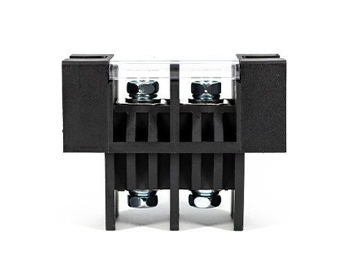
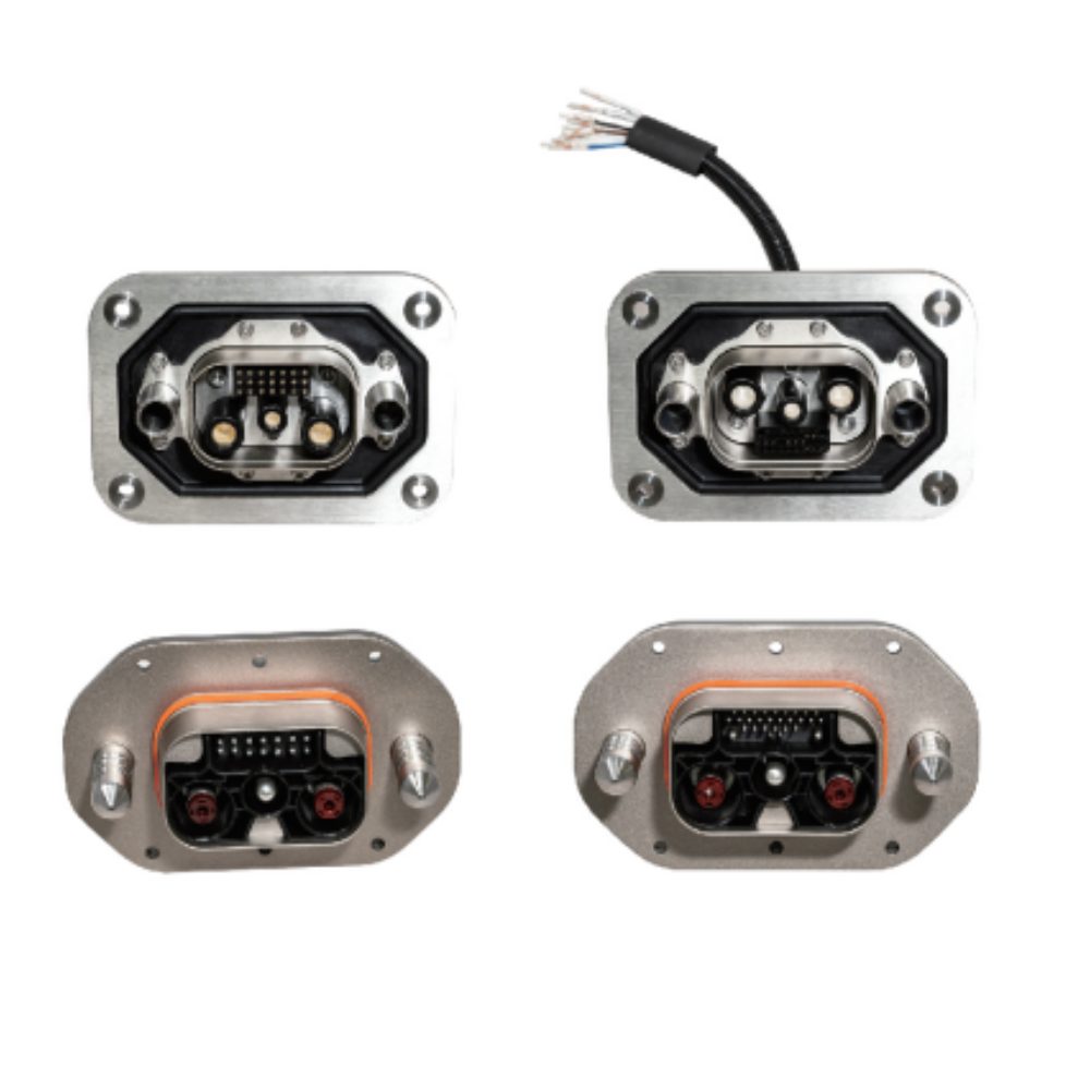
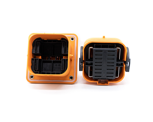
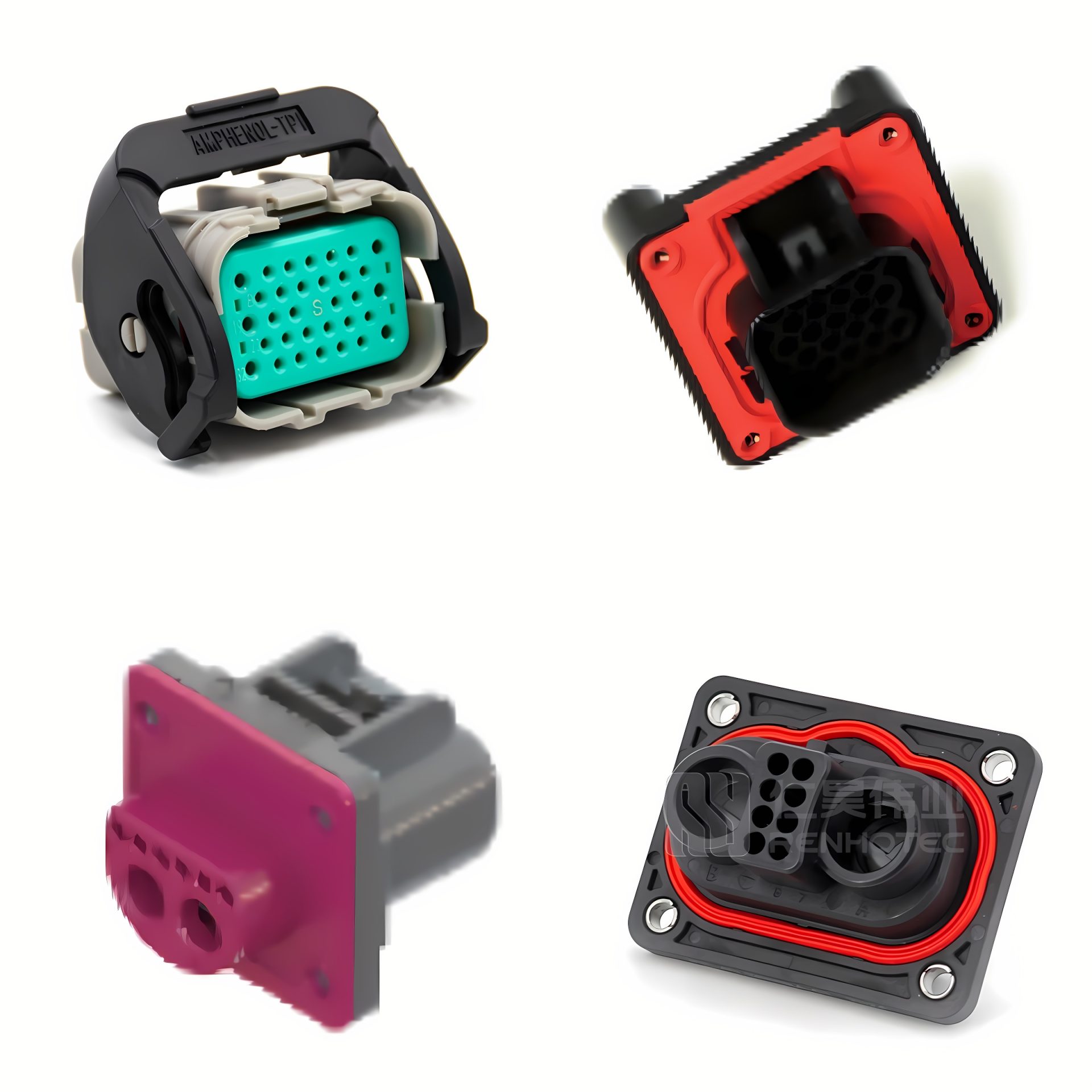
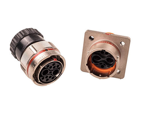
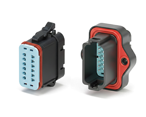
The Rectangular Connector is widely used in aerospace, medical instruments, consumer electronics (such as computers, TVs, game consoles, etc.), industrial control equipment, communication equipment, and automotive electronics. With its reliable connection performance, diverse specifications, and relatively convenient plug-in and unplug operations, it has become an indispensable component in various electronic and electrical applications.
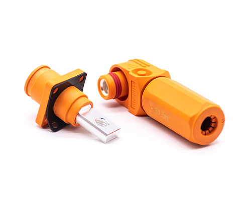
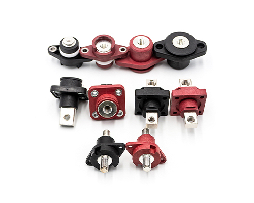
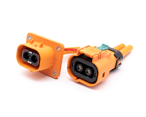
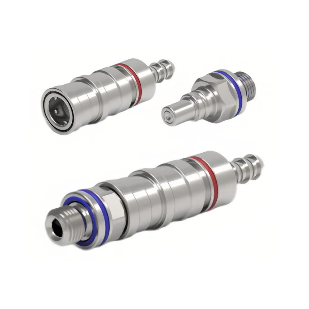
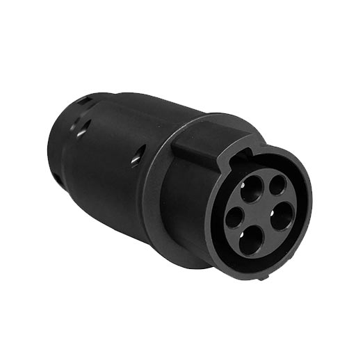
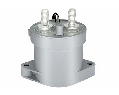
High Voltage Connectors are widely used in EV power systems, renewable energy installations, and industrial high-voltage circuits. Renhotec’s series drives the building of efficient, safe, and sustainable electrical ecosystems, meeting current technological demands.
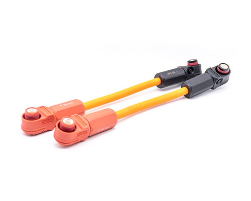
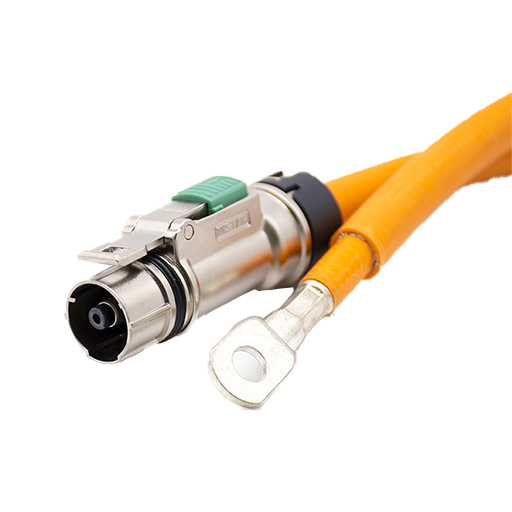
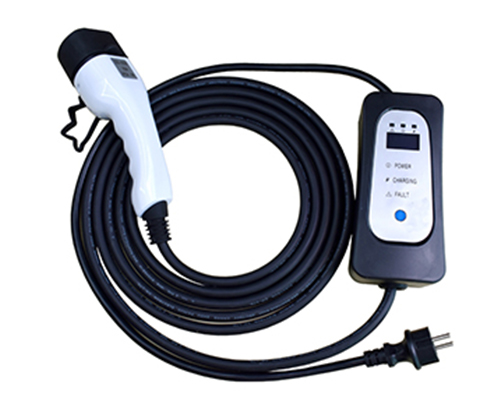
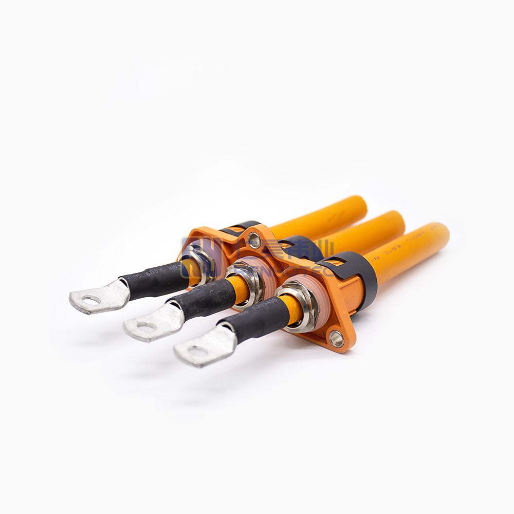
Renhotec EV Cable, crafted with top-notch conductive materials and meticulously engineered insulation, showcases outstanding impedance control and voltage-withstanding properties. Its design combines flexibility and durability to meet a wide array of installation needs. This cable is widely utilized in grid interconnections, large-scale industrial power supply systems, and high-voltage renewable energy projects, enabling smooth and efficient power transmission.
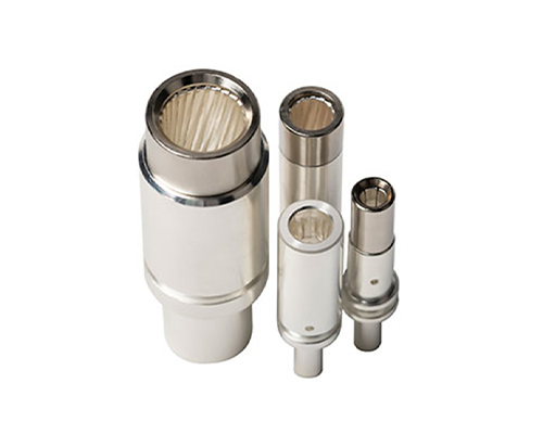
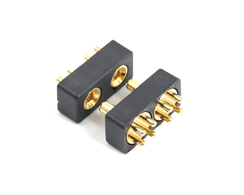
Renhotec, as a professional supplier, offers a comprehensive range of these Signal Transmission Connector products. Whether it is the high-reliability applications of the metal series or the wide adaptability of the plastic series in consumer electronic products, Renhotec can provide customers with high-quality options to meet the diverse requirements of signal transmission connections in different industries and scenarios.
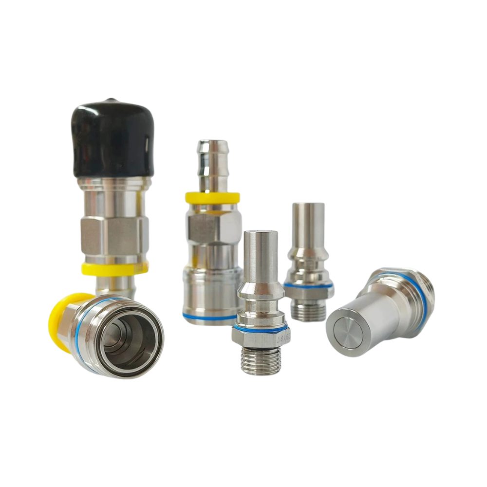
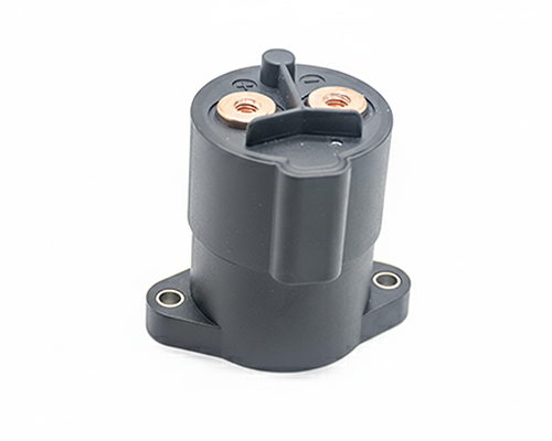
Renhotec, active in electrical components, offers High Voltage DC Contactors in Epoxy Resin Sealing and Ceramic Sealing variants, with a 20A – 1000A current range. The Epoxy Resin Sealing one is cost-effective and protective. The Ceramic Sealing variant excels in thermal stability and insulation. They’re widely used in EV charging, renewable energy grid, and industrial high-voltage DC power distribution for reliable circuit control and current interruption, providing comprehensive solutions for multiple sectors.
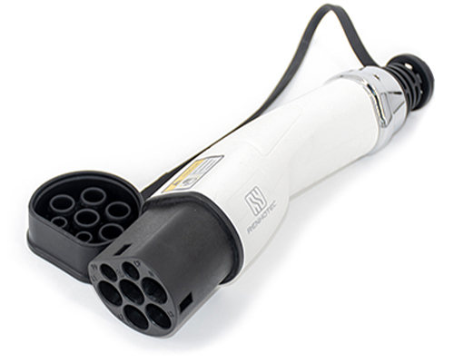
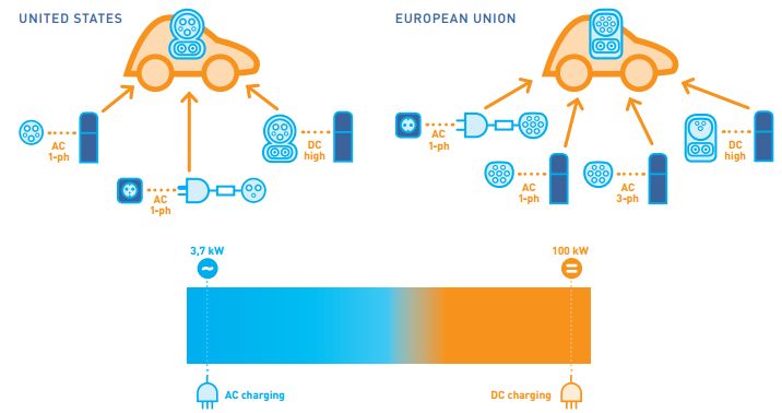
With the rapid development of the global electric vehicle industry, various countries are speeding up the construction of electric vehicle charging piles. However, the EV charging connector types vary from country to country, which to a certain extent affects the convenience of EV charging.
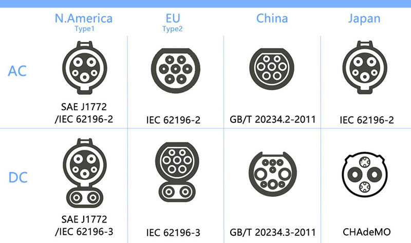
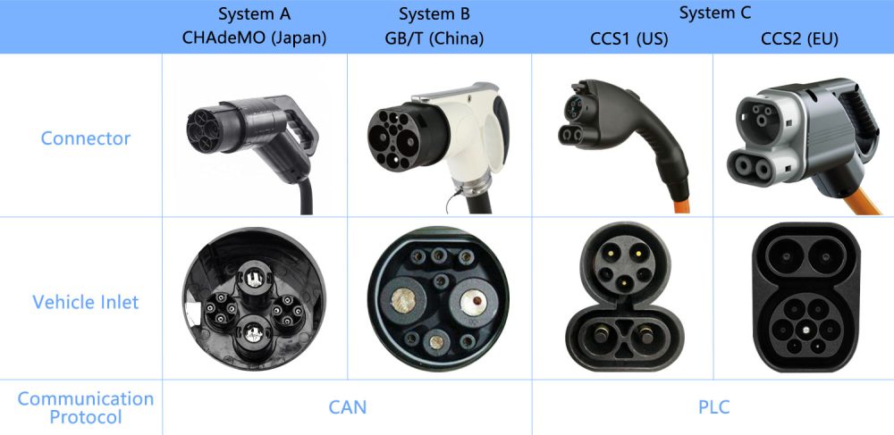
EV charging connector standards differ across regions. North America mainly uses CCS1 and NACS, Europe uses Type 2 and CCS2, China follows the GB/T standard system, and Japan traditionally uses CHAdeMO.
In recent years, major automakers like Ford, GM, and Rivian have adpoted Tesla’s NACS (Niorth American Charging Standard). This connector has been recognized as SAE J3400. It’s becoming the unified standard for North America, gradually replacing CCS1 for new electric vehicles.
China is also rapidly advancing ultra-fast EV charging technologies. Companies like BYD are developing megawatt-level flash charging solutions based on the GB/T charging system, supporting charging power above 1 MW through high-voltage platforms and liquid-cooled charging connectors.
Figure 1: EV Charging Plug Types Around the World
SAE J1772 Standard
SAE J1772 is a North American standard for electrical connectors for electric vehicles maintained by the SAE International and has the formal title “SAE Surface Vehicle Recommended Practice J1772, SAE Electric Vehicle Conductive Charge Coupler”.
There’re several common IEC connector types. IEC 62196 is an international standard for set of electrical connectors and charging modes for electric vehicles and is maintained by the International Electrotechnical Commission (IEC).
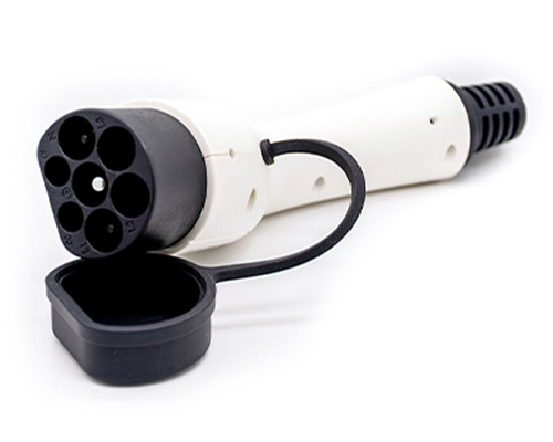
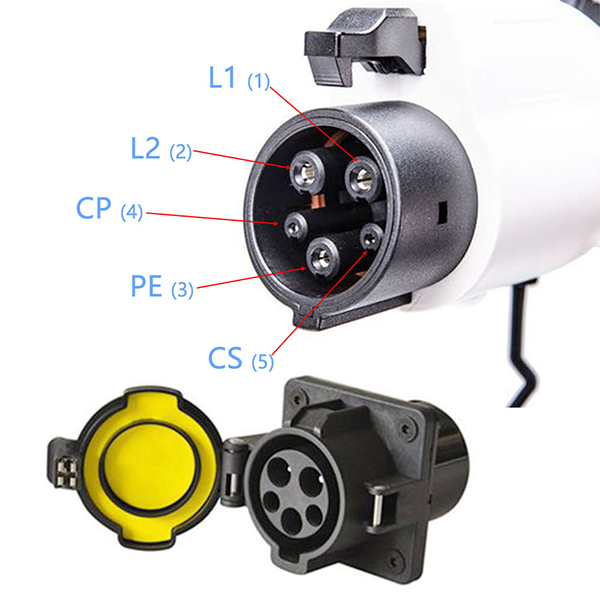
The IEC 62196 standard type 1 charging connector contact definition is the same as the SAE J1772 standard AC charging interface, as shown in Figure 2.
Table 3: Maximum voltage and current for each contact according to IEC 62196 Type 1
PIN ③
AC
Functions ①
1
250V 32A ②
L1 (mains 1)
2
250V 32A
L2 (mains 2) / N (neutral)
3
Rated for fault
PE (ground / earth)
4
30V 2A
CP (Control pilot)
5
30V 2A
CS (Connection switch)
① For contacts 4 and 5, environmental conditions may demand larger conductor cross-sections. ② In the following countries, the branch circuit overcurrent protection is based upon 125% of the device rating: USA. ③ Positon number does not refer to the location and/or identification of the contact in the accessory.
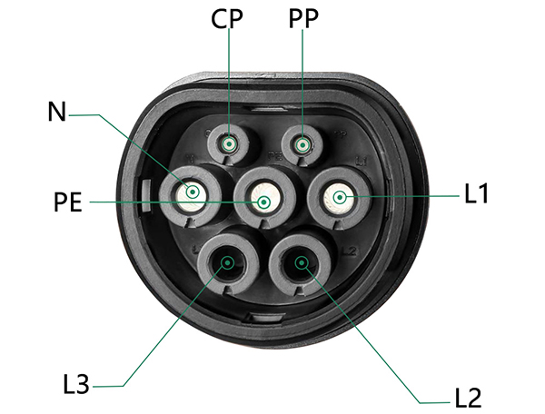
The type 2 charging connector contact definition of the IEC 62196 standard is shown in Figure 3.
Figure 3: PIN of IEC 62196 Standard EV Charging Plug
Charging power pins: line (L1), line (L2), line (L3), neutral(N), and protective earth (PE). Signal pins: the control pilot (CP) and proximity pilot (PP).
The maximum voltage and current of the IEC 62196 standard charging connector in three-phase and single-phase power are shown in Table 3.
Table 4: Maximum voltage and current for each PIN according to IEC 62196 in three-phase power and single-phase power
PIN ⑥
Three phase
Single phase
Functions
Umax
Imax ①
Imax ①
V a.c.
A
A
Type 2
Type 3
Type 2 ②
Type 3
1
500
63
32
70
32
L1 (mains 1) ②
2
500
63
32
– ③
– ③
L2 (mains 2)
3
500
63
32
– ③
– ③
L3 (mains 3)
4
500
63
32
70
32
N (neutral) ②③
5
—
Rated for fault
PE (ground / earth)
6
30
2
CP (Control pilot)
7
30
2
PP (Proximity) ④ or CS (Connection switch) ④
① In the following countries, the branch circuit overcurrent protection is based upon 125% of the device rating: USA. ② For single phase charging contacts 1 and 4 shall be used. ③ Unused contacts need not to be installed. Not provided for standard sheets 2-llla and 2-lllb. ④ Not provided for standard sheet 2-llla. ⑤ For single phase system supply phase to phase this contact can be used for L2 (mains 2). ⑥ Position number does not refer to the location and/or identification of the contact in the accessory.
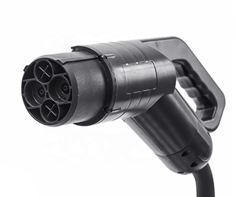
CHAdeMO Standard
CHAdeMO was formed by The Tokyo Electric Power Company, Nissan, Mitsubishi and Fuji Heavy Industries. Toyota later joined as its fifth executive member. Three of these companies have developed electric vehicles that use TEPCO‘s DC connector for quick charging.
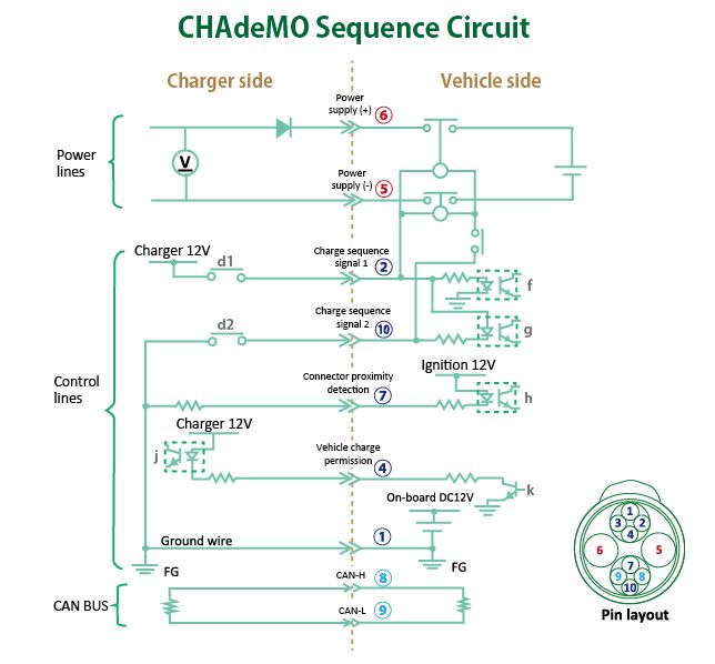
The contact definition of the charging connector of the CHAdeMO standard can be seen in Table 5, while Figure 4 shows the timing circuit of the CHAdeMO.
Table 5: CHAdeMO Pin Assignment
PIN
Functions
1
Ground
2
Charge sequence signal
3
Not connected
4
Charging permission
5
DC+ power
6
DC- power
7
Connector proximity detection
8
CAN high
9
CAN low
10
Charging sequence signal
Figure 4: CHAdeMO EV Charging Connector Sequence Circuit
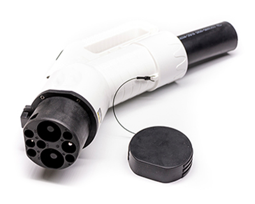
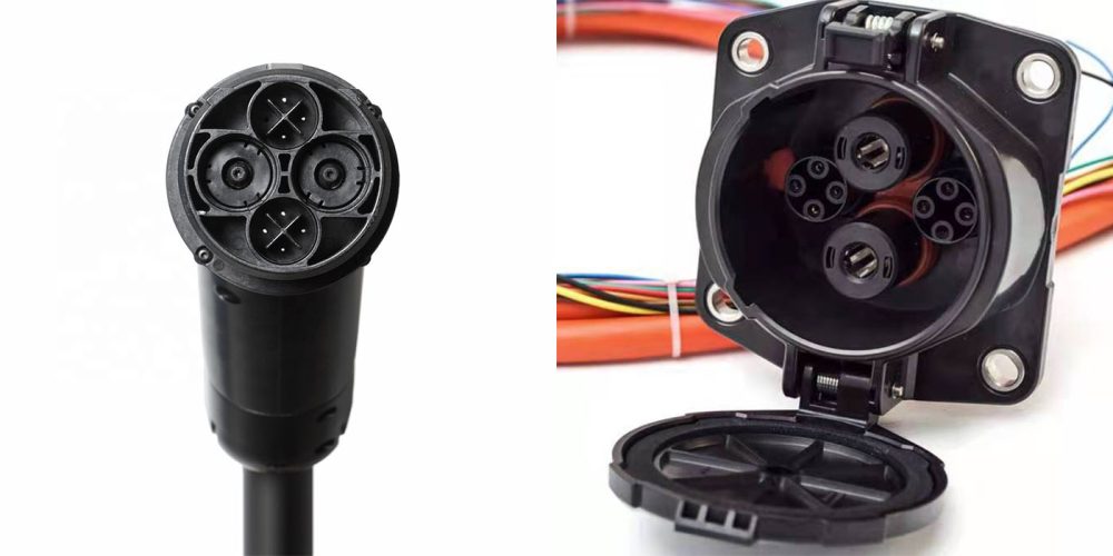
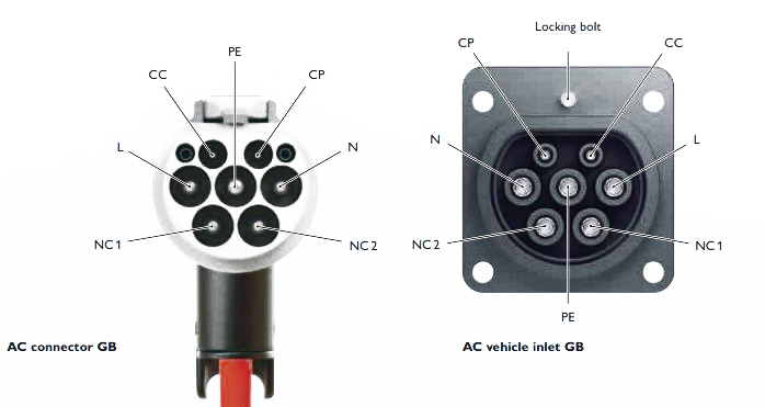
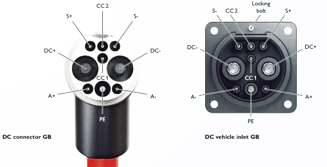
The GB/T 20234.1,2,3-2011 standard has an AC charging connector as shown in Figure 6, a DC charging connector as shown in Figure 7, and a maximum voltage and current and insulation level as shown in Figure 7. GB’s DC charging also uses CAN communication.
Figure 6: EV Charging Connector of GB/T Standard (AC )Figure 7: EV Charging Connector Pinout of GB/T Standard (DC )
Table 6: AC and DC charging system according to GB standard
Parameter
AC
DC
GB standard
Nominal voltage
Up to 440 V AC
Up to 1000 V DC
Nominal current
Up to 32 A
Up to 600 A
Standard
GB/T 20234.2
GB/T 20234.3
IP protection when plugged in
IP55
IP55
IP protection with protective cap
IP54
IP54
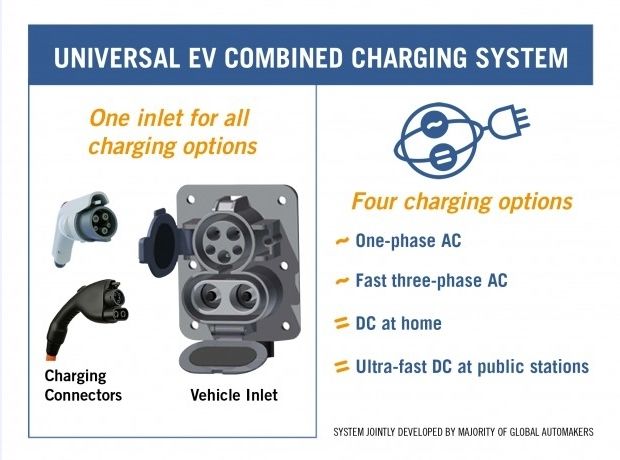
Combined Charging System (CCS) Standard
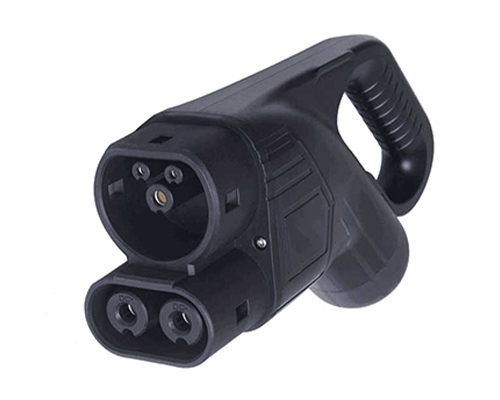
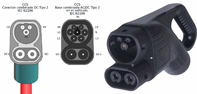
The Combined Charging System is a quick charging method for battery electric vehicles delivering high-voltage direct current via a special electrical connector derived from the SAE J1772 (IEC Type 1) or IEC Type 2 connector. As the plug is a combination of an AC connector with a DC option the resulting connector is also called Combo Coupler and the variant with Type 2 is abbreviated as Combo2.
The eight major American and German manufacturers, Ford, GM, Chrysler, Audi, BMW, Mercedes-Benz, Volkswagen and Porsche, released the “Joint Charging System” in 2012. All current charging interfaces are unified so that four modes of single-phase AC charging, fast three-phase AC charging, home DC charging, and super-speed DC charging can be accomplished with one interface. The charging plug of the combined type using the SAE J1772 standard is shown in Figure 8. Figure 9 shows the combined charging plug with charging using IEC 62196 standard. Figure 10 shows the schematic diagram of combined charging and power information.
Figure 8: Universal CCS EV Charging Connector SystemFigure 9: CCS2 EV Charging Connector Pinout According to IEC 62196Figure 10: Schematic Diagram of CCS Charging and Power Information
The communication protocol for combined charging uses power carrier communication, PLC (power line communication). While GB/T and CHAdeMO use CAN communication.
Figure 11: The Communication Protocol for EV Charging Connectors
Summary
Each EV charging standard has evolved to meet the needs of different regional markets and vehicle platforms. CCS and NACS are becoming the dominant fast-charging standards in North America and Europe, China continues to advance the GB/T ecosystem with ultra-high-power charging technologies, while CHAdeMO is gradually declining outside Japan.
Although global EV charging standards are still not fully unified, the industry is rapidly moving toward higher charging power, better interoperability, and broader international compatibility.
People Also Ask
Q: Can I use a Type 2 charger on a Type 1 car? A: No, not directly. You will need a specific Type 2 to Type 1 adapter. However, most public charging stations usually provide cables or sockets that match specific regional standards.
Q: What is the difference between AC and DC charging connectors? A: AC connectors (like Type 1 and Type 2) use the vehicle’s onboard charger to convert power, making them slower. DC connectors (like CCS and CHAdeMO) bypass the onboard charger, delivering high voltage directly to the battery for rapid charging.
Q: Is CHAdeMO being phased out? A: Outside of Japan, CHAdeMO is gradually being replaced by the CCS 2 connector (Europe) and CCS 1/NACS (North America) standards. However, many legacy vehicles (like Nissan Leaf) still rely on it.
Q: How to select the correct charging plug types for commercial charging stations?
A: Choosing the appropriate EV charging plug types requires evaluating three core technical parameters: the regional compliance standard (e.g., CE, UL, or TUV certification), the charging phase requirements (single-phase vs. three-phase), and the exact electrical ratings (maximum current and voltage capacity). Always cross-reference your specific project requirements with the manufacturer’s specification tables.
2 thoughts on “EV Charging Connector Types Worldwide”
Having difficulty finding the detailed schematics for Iec62196ev connector I want to know what the power is on the pins and schematic on the detection pins can you help Ray


Does anyone have a list of countries and the type of charging station connectors used there ?
Having difficulty finding the detailed schematics for Iec62196ev connector I want to know what the power is on the pins and schematic on the detection pins can you help Ray