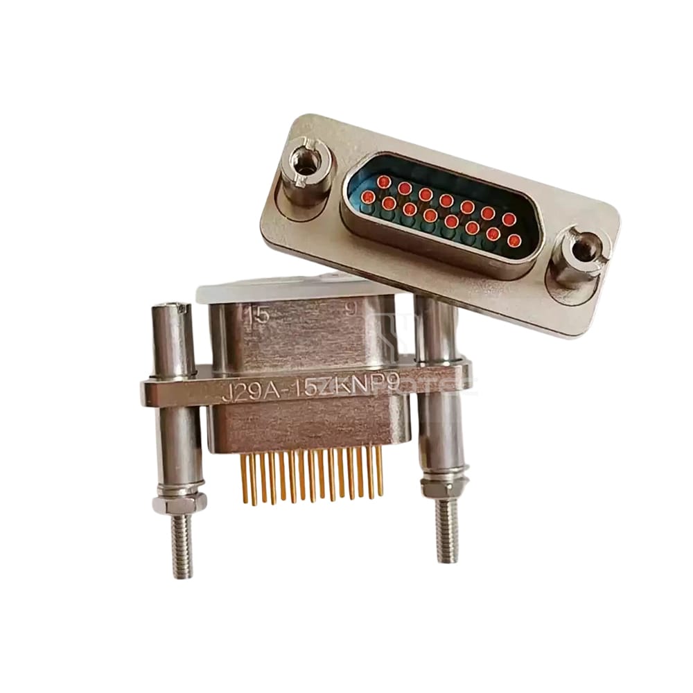
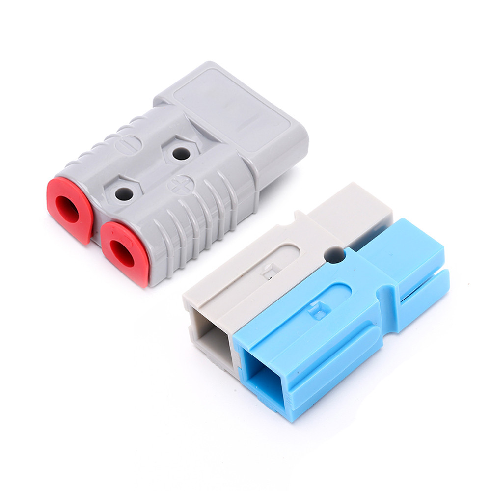
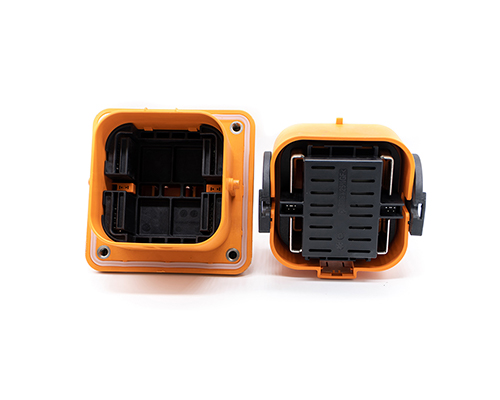
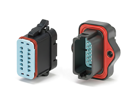
The Rectangular Connector is widely used in aerospace, medical instruments, consumer electronics (such as computers, TVs, game consoles, etc.), industrial control equipment, communication equipment, and automotive electronics. With its reliable connection performance, diverse specifications, and relatively convenient plug-in and unplug operations, it has become an indispensable component in various electronic and electrical applications.
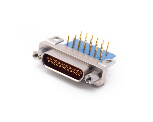
J30J General Connectors and Cable Assemblies
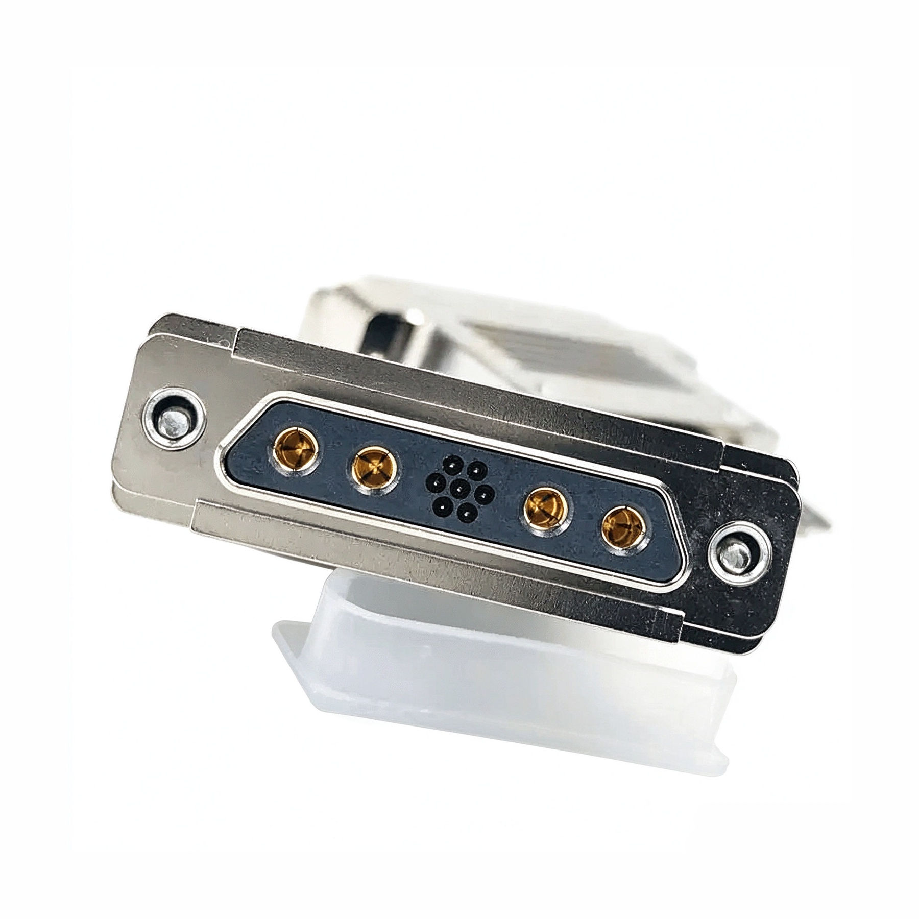
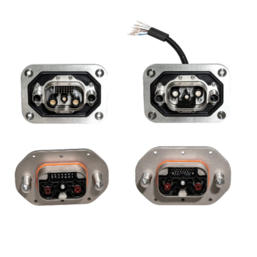
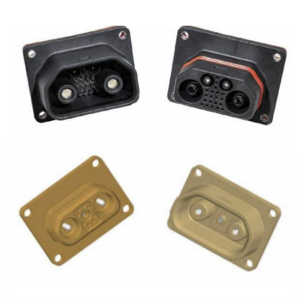
J30J Mixed Current (Hybrid) Connectors and Cable Assemblies
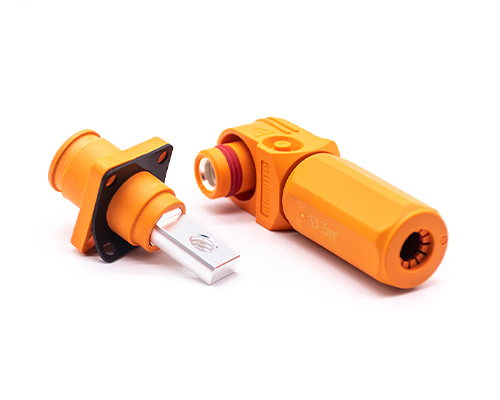
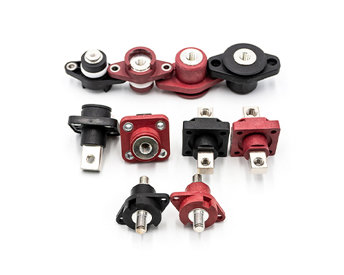
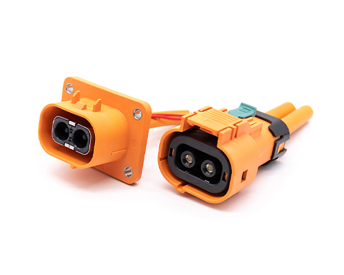
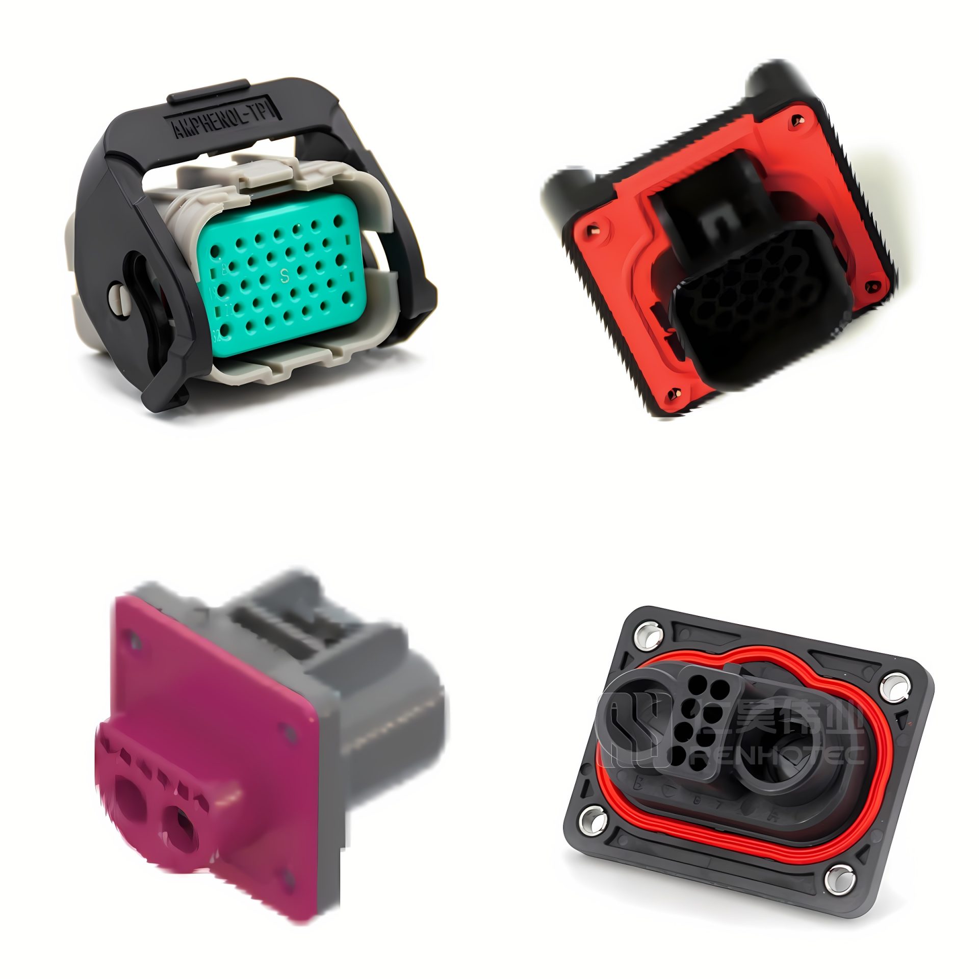
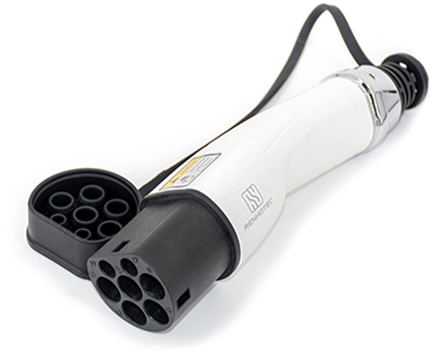
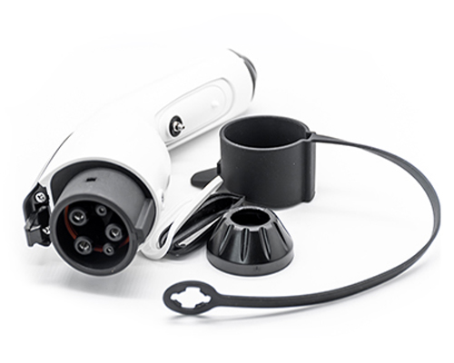
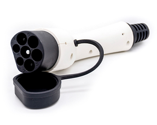
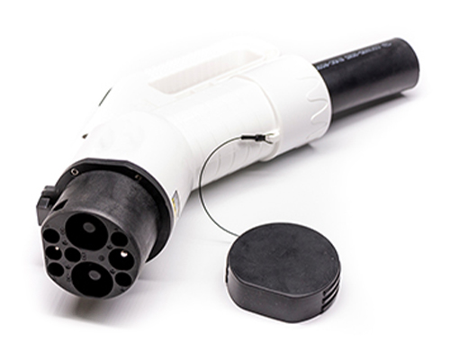
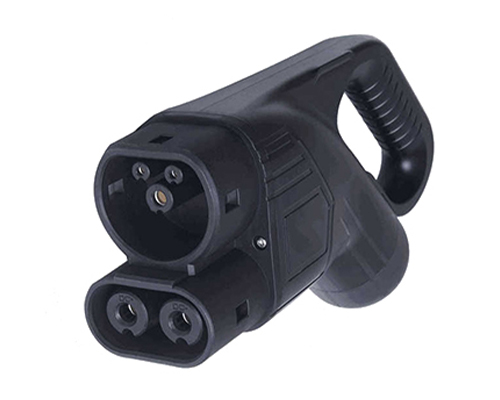
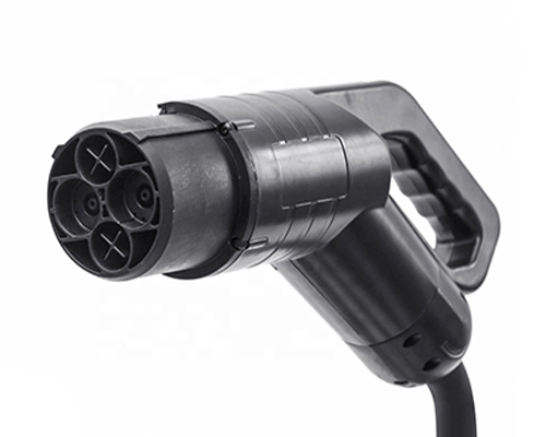
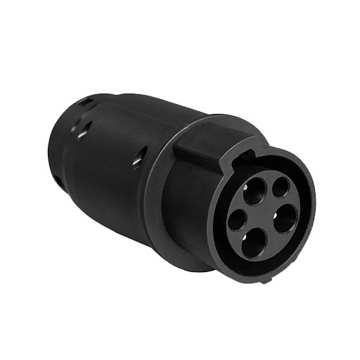
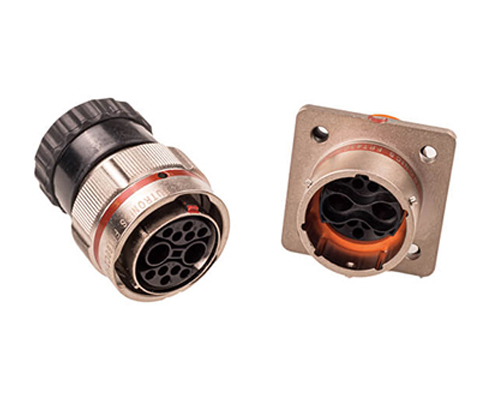
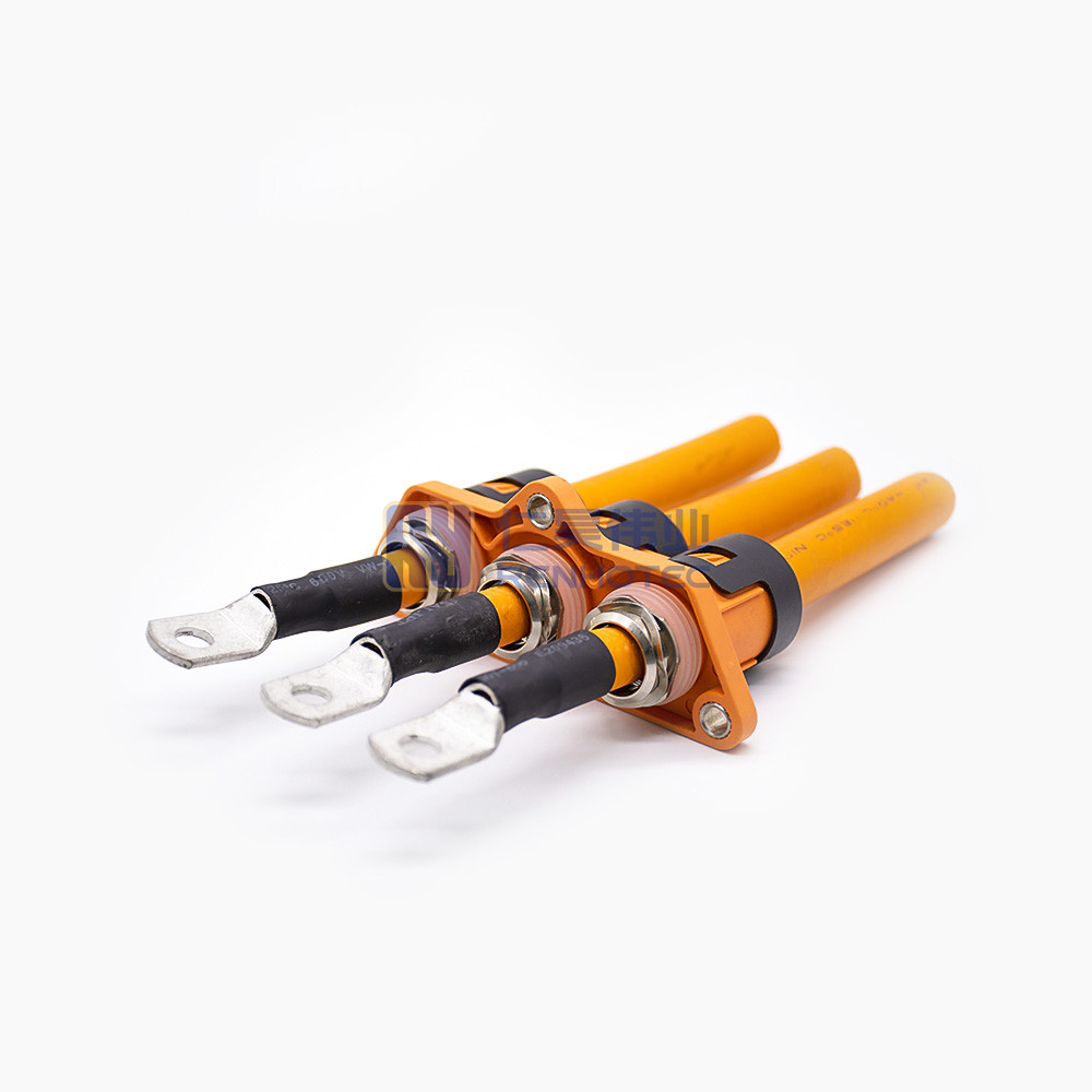
High Voltage Connectors are widely used in EV power systems, renewable energy installations, and industrial high-voltage circuits. Renhotec’s series drives the building of efficient, safe, and sustainable electrical ecosystems, meeting current technological demands.
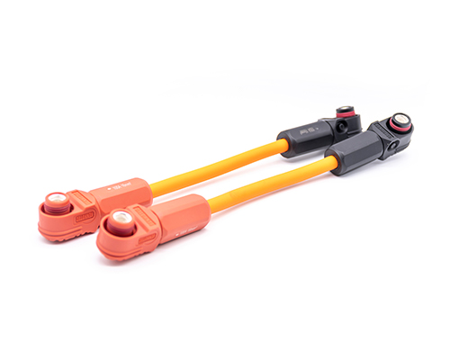
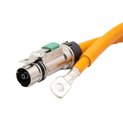
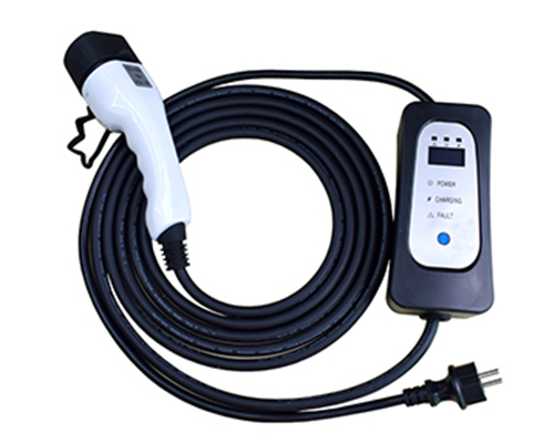
Renhotec EV Cable, crafted with top-notch conductive materials and meticulously engineered insulation, showcases outstanding impedance control and voltage-withstanding properties. Its design combines flexibility and durability to meet a wide array of installation needs. This cable is widely utilized in grid interconnections, large-scale industrial power supply systems, and high-voltage renewable energy projects, enabling smooth and efficient power transmission.
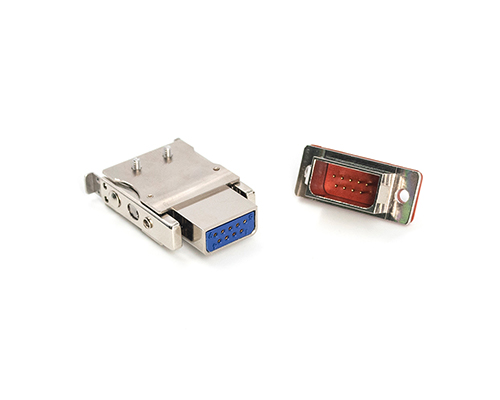
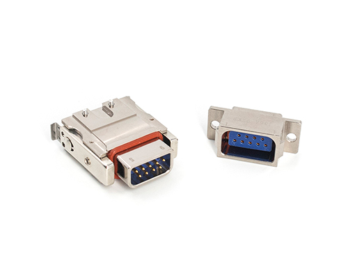
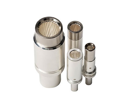
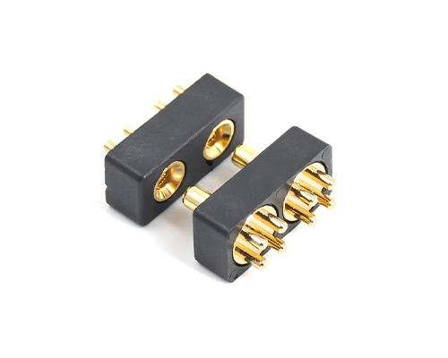
Renhotec, as a professional supplier, offers a comprehensive range of these Signal Transmission Connector products. Whether it is the high-reliability applications of the metal series or the wide adaptability of the plastic series in consumer electronic products, Renhotec can provide customers with high-quality options to meet the diverse requirements of signal transmission connections in different industries and scenarios.
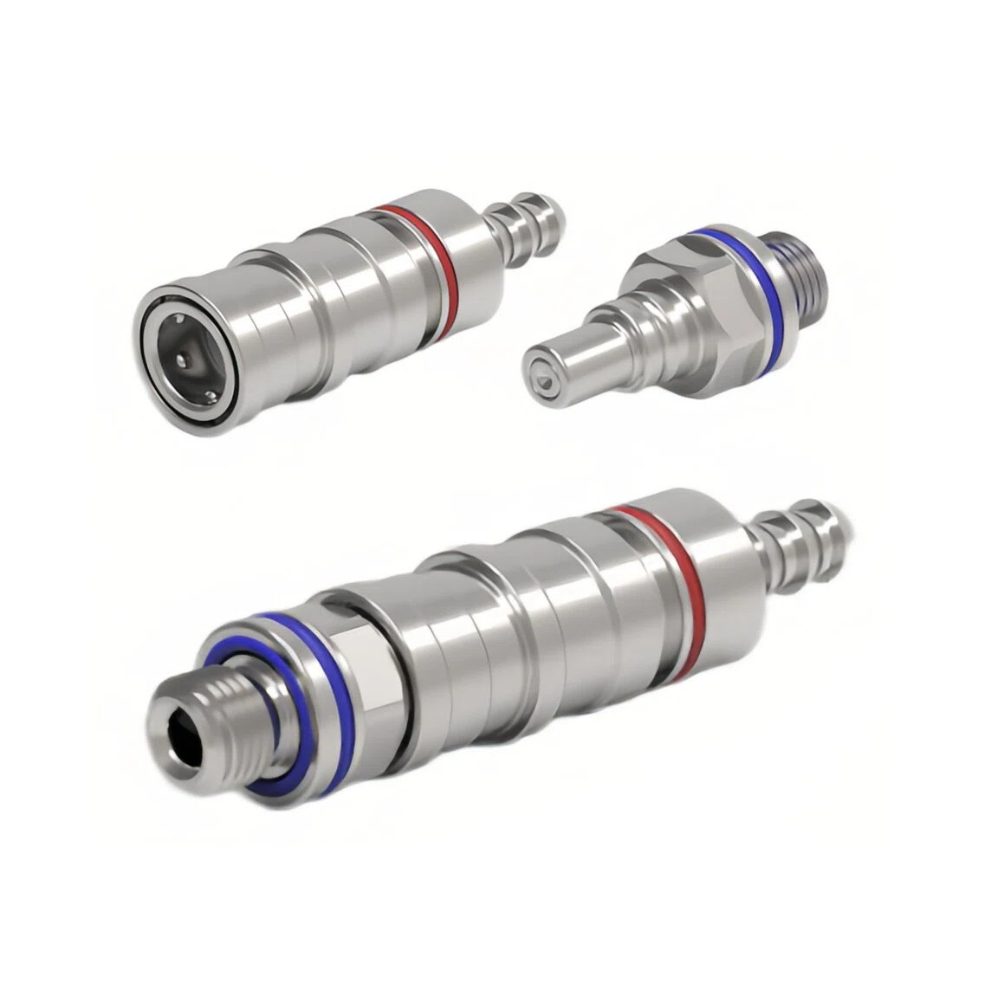
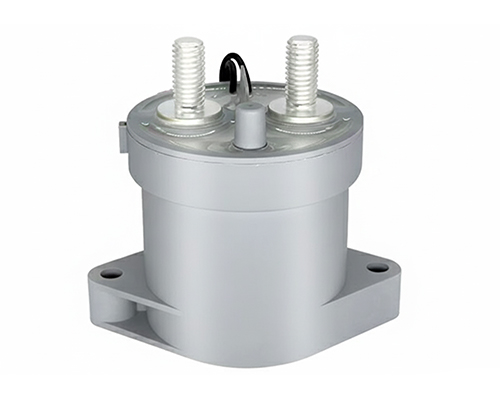
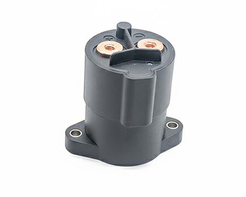
Renhotec, active in electrical components, offers High Voltage DC Contactors in Epoxy Resin Sealing and Ceramic Sealing variants, with a 20A – 1000A current range. The Epoxy Resin Sealing one is cost-effective and protective. The Ceramic Sealing variant excels in thermal stability and insulation. They’re widely used in EV charging, renewable energy grid, and industrial high-voltage DC power distribution for reliable circuit control and current interruption, providing comprehensive solutions for multiple sectors.
A J30J connector part number looks like a random string of letters and numbers — until you realize that every character sits in a fixed position and carries exactly one piece of ordering information. Read it left to right and you can tell the shell, pin count, contact gender, termination style, locking hardware and any factory modifications — without opening a datasheet. This guide breaks the code down field by field, then decodes a complete real-world example.
A fully expanded code with every option filled in can look long, but the most common configurations are surprisingly short. J30J-21TJL is a 21-pin plug with pin contacts and an L-type locking assembly for a free cable end; J30J-15ZKW is a 15-pin receptacle with socket contacts and right-angle PCB tails. Both are complete, orderable part numbers — the optional fields are simply left blank.
A standard J30J ordering code has up to eight segments, followed by an optional note in parentheses:
Only three fields are mandatory: the series and shell (1), the contact count (3), and the connector type and gender (4). Fields 2, 5, 6, 7 and 8 are optional — a blank field selects the factory default.
Two reading rules help. Fields are positional: the contact count always comes right before TJ or ZK, the termination right after. And modification codes in field 7 can stack: AD means modification A plus modification D.
Blank — basic type A — quick-lock E — short shell R — reverse gender (plug takes sockets) G — high-temperature (up to 185 °C) M — rubber seal M1 — glass-sintered hermetic D — shell through-holes changed to M2 threaded holes
X
Number of contacts
9, 15, 21, 25, 31, 37, 51, 66, 74, 100, 144
TJ / ZK
Connector type and contact gender
TJ — plug with pin contacts ZK — receptacle with socket contacts TK — plug with sockets / ZJ — receptacle with pins (the reverse-gender pair, normally used together with R)
X
Termination style
Blank — crimp S — solder cup N — straight PCB, 2.54 × 2.54 mm grid W — right-angle PCB, 2.54 × 2.54 mm grid N3 / N4 / N8 / N12 — straight PCB with longer tails (6.7–8 mm) W6 — right-angle PCB with longer tail Add J for 1.27 × 2.54 mm grid versions
X–
Locking and mounting hardware
Blank — default hardware (see the rules below) Y — supplied without hardware L, K — free-end locking assembly P, V — fixed-end locking assembly P5 / P7 — PCB-mount types
X
Modification codes (can stack)
A — shielding sleeve with cable clamp (crimp only) A5 — as A, plus a tail clamp plate C — 90° wire exit; C1 / C2 — exit-direction variants D — anti-rotation slot (fixed-end only) D2 — screw-compression spring lock G — cadmium-plated shell J — 1.27 × 2.54 mm PCB grid Q, Q8 — widened flange; (9.6) / (11.6) — flange width in mm
X
Accessory code
A1 — cable clamp (crimp and solder types) A2 — cable clamp for Q8 shells only A3 — clamp attachment (crimp and solder types)
Worked Example: J30J-31ZKPGAD(11.6)
Here is the code broken down segment by segment:
Segment
Reading
J30J
Basic series, nickel-plated aluminum shell
31
31 contacts
ZK
Receptacle with socket contacts
(blank)
Crimp termination — the blank field selects the default
P
Fixed-end (panel-mount) locking assembly
GAD
Three stacked modifications: cadmium-plated shell (G), shielding sleeve with cable clamp (A), anti-rotation slot (D)
(11.6)
Flange widened to 11.6 mm
(AFR-250, 0.12 mm², 300 mm)
Wire note: AFR-250 wire, 0.12 mm² cross-section, at least 300 mm long, with a nylon braid over the bundle
Every character is accounted for: a 31-contact receptacle, crimp-terminated, with panel-mount locking hardware, cadmium-plated shell, shielding and anti-rotation features, an 11.6 mm flange and a fully specified wire bundle. One caution: the mixed-current J30J combo series uses its own numbering system — the J30J combo guide covers that separately.
Five Details the Basic Table Doesn’t Show
1. A blank locking field does not mean “no hardware”
J30J connectors ship with locking assemblies mounted unless you say otherwise. The default depends on the connector style:
Connector style
Default locking assembly
Crimp or solder plug (free end)
L type
Crimp or solder receptacle (fixed end)
P type
Right-angle PCB version
P7 type
Straight PCB version
P5 type
If you do not want hardware, order with the Y code or state it explicitly in the contract — otherwise the default assembly will arrive mounted.
2. PCB tail codes match your board thickness
The plain N code is a straight PCB tail on a 2.54 × 2.54 mm grid. The numbered variants N3, N4, N8 and N12 carry longer tails (about 6.7 to 8 mm) for thicker boards or deeper solder joints, and W6 does the same for the right-angle version. If your layout is tight, look for the J suffix — it switches the PCB grid to 1.27 × 2.54 mm, roughly halving the footprint width.
3. Spell out the wire spec in the parenthetical
For pre-wired connectors, the note in parentheses should state the wire type (for example AFR-250), the cross-section (0.1–0.15 mm² recommended), the minimum length, and the color. Two defaults are worth knowing: every position is crimped with wire unless you say otherwise, and wire color is free but must be consistent within one batch. For non-standard routing, provide a wiring table instead of a verbal description.
4. Accessory codes add clamps after the main code
A1 and A3 are tail cable-clamp accessories for crimp and solder types; A2 is the clamp for Q8 widened-flange shells. They appear as a suffix after the modification codes — a clamped, shielded plug can end in something like A-A1.
5. Not every J30J maker uses identical codes
The J30J series performs to GJB2446A-2011 (equivalent to MIL-DTL-83513), and individual manufacturers place some codes differently — stainless steel appears as a series-level suffix (J30JS) in one catalog and as a modification letter in another. When you cross-reference against ITT Cannon MDM or Glenair MWDM part numbers, treat code comparisons as a starting point and confirm the final part number with the supplier’s current catalog before ordering. The J30J family also extends well beyond the basic style decoded here — hermetic, filtered, combo and other derivative versions each carry their own ordering rules. For an overview of the main styles, see our J30J connector variants comparison.
J30J Key Specifications
The part number describes the mechanical build; these are the electrical and environmental figures behind it:
Parameter
Value
Rated current
3 A per contact
Operating temperature
-55 °C to +125 °C
Dielectric withstanding voltage
800 V
Insulation / contact resistance
≥ 5000 MΩ / ≤ 10 mΩ
Mechanical life
500 mating cycles
Wire range (crimp)
0.035–0.2 mm² (0.1–0.15 mm² recommended)
Standard
GJB2446A-2011, equivalent to MIL-DTL-83513
Before You Order: Quick Checklist
Still choosing a connector family rather than decoding an existing code? Start with our Micro-D connector selection guide. Once you have a J30J code in hand, run this check:
Pin count and layout — the contact arrangement differs by count; confirm the layout drawing, not just the number.
Termination matches your process — crimp (check wire gauge against 0.1–0.15 mm²), solder cup, or PCB tail length for your board thickness.
Locking hardware — accept the default L/P/P5/P7 assembly, name a specific type, or add Y to exclude it.
Stacked modifications — combinations like AD (clamp plus anti-rotation) must appear together in field 7.
The parenthetical — wire type, cross-section, minimum length, and color requirement, written explicitly.
Final cross-check — verify the complete code against the supplier’s current catalog or the J30J Micro-D series page before releasing the order.
Need a J30J built to your exact code?
Send us the part number — or just your pin count, termination, and wiring requirements — and we will confirm the full ordering code, hardware, and lead time. Contact our team for a quote.
Sources and Standards
Where manufacturers implement the series differently, their own documentation takes precedence.