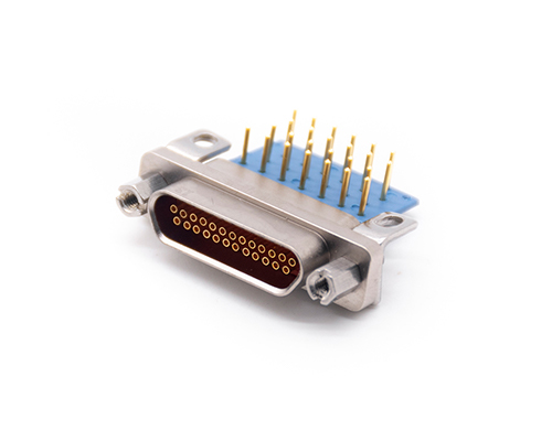
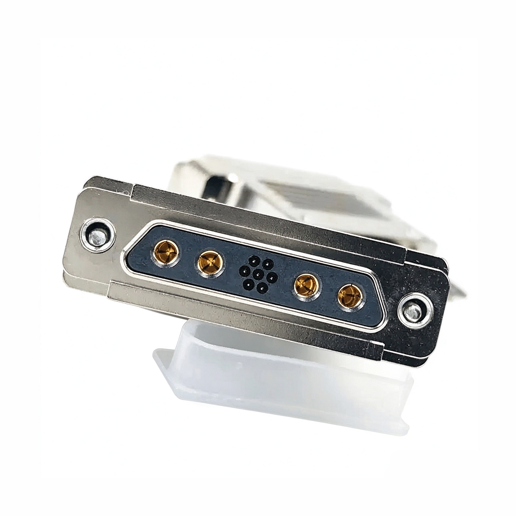
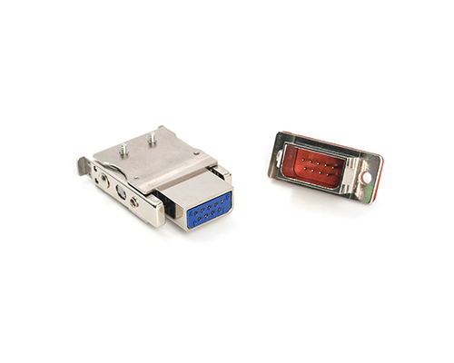
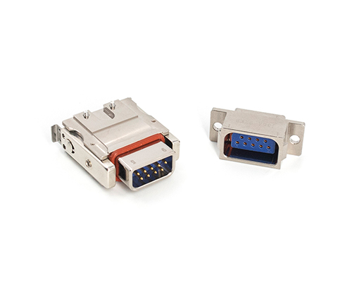
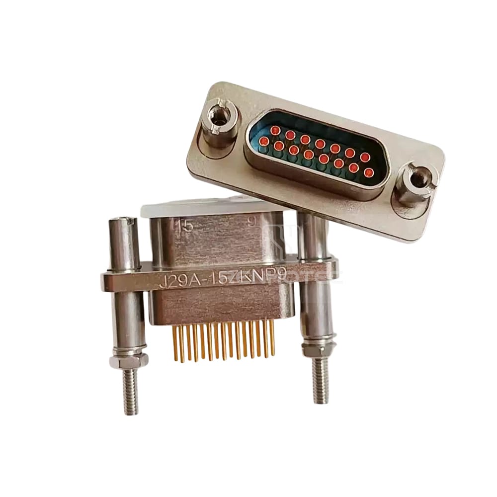
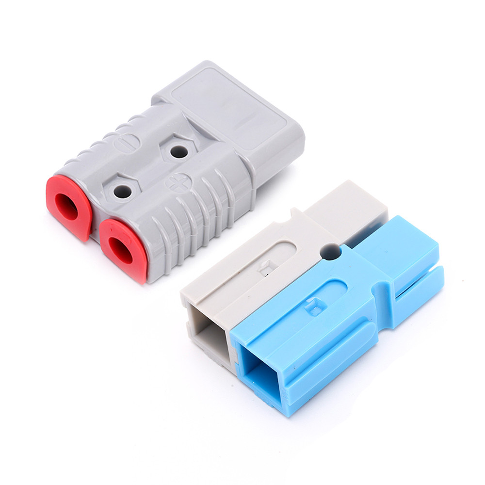
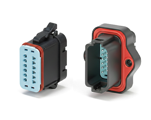
The Rectangular Connector is widely used in aerospace, medical instruments, consumer electronics (such as computers, TVs, game consoles, etc.), industrial control equipment, communication equipment, and automotive electronics. With its reliable connection performance, diverse specifications, and relatively convenient plug-in and unplug operations, it has become an indispensable component in various electronic and electrical applications.
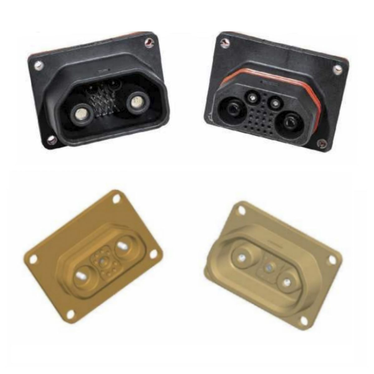
J30J General Connectors and Cable Assemblies
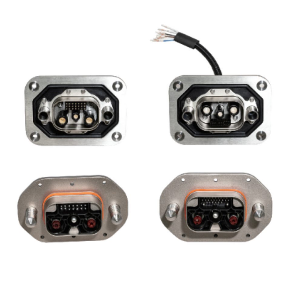
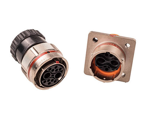
J30J Mixed Current (Hybrid) Connectors and Cable Assemblies
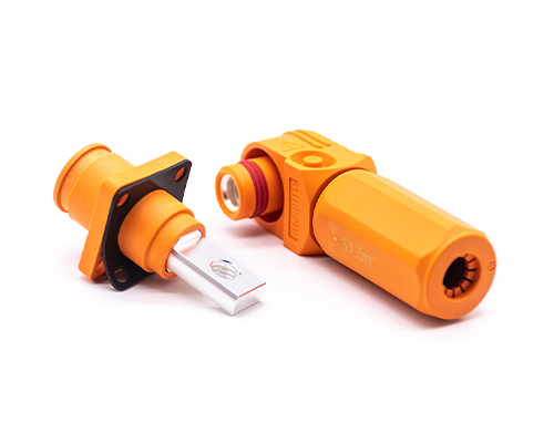
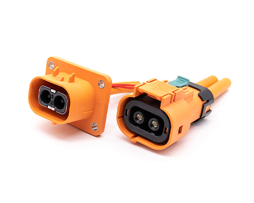
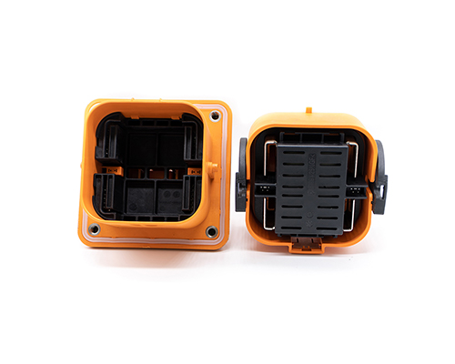
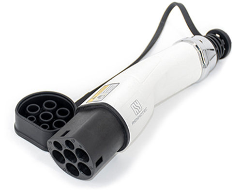
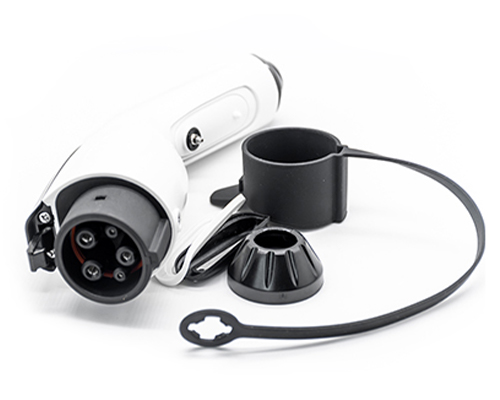
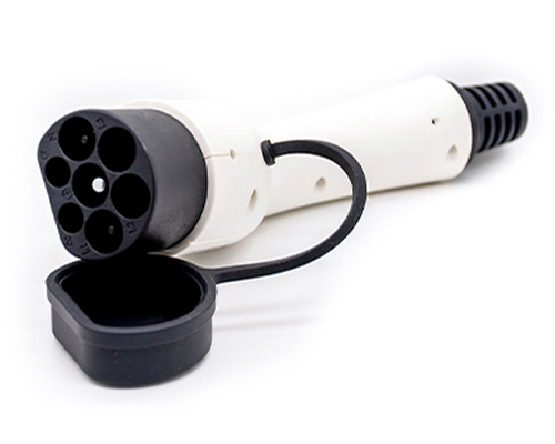
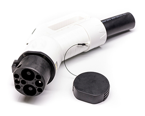
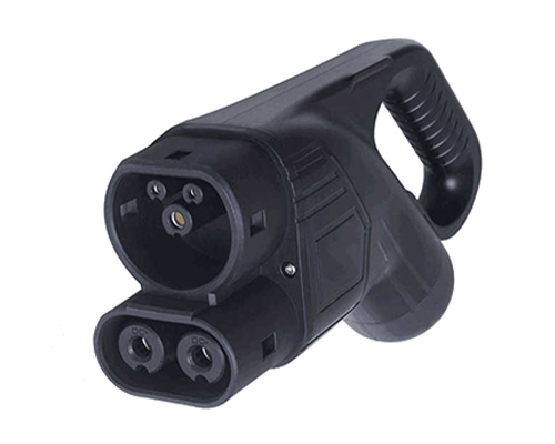
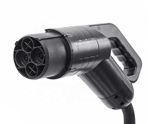
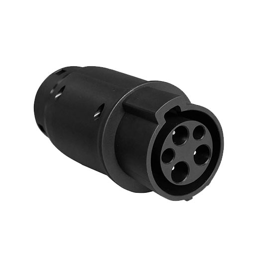
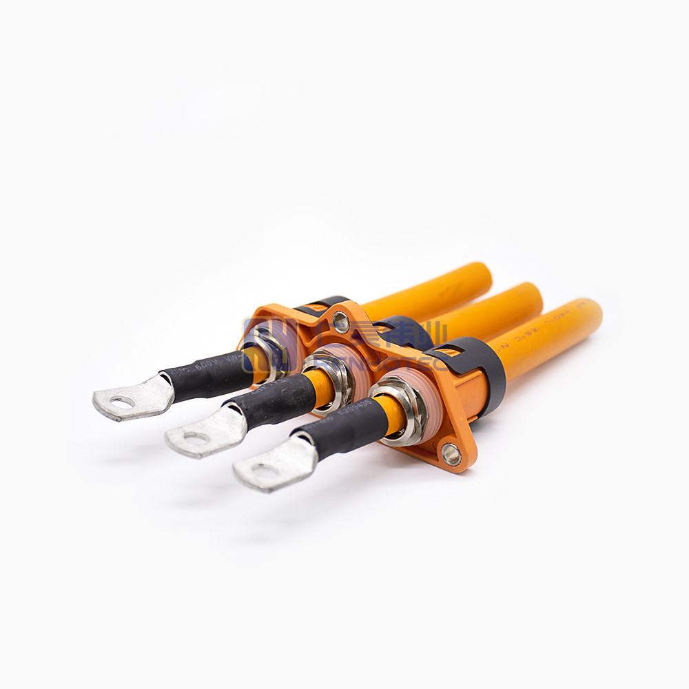
High Voltage Connectors are widely used in EV power systems, renewable energy installations, and industrial high-voltage circuits. Renhotec’s series drives the building of efficient, safe, and sustainable electrical ecosystems, meeting current technological demands.
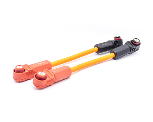
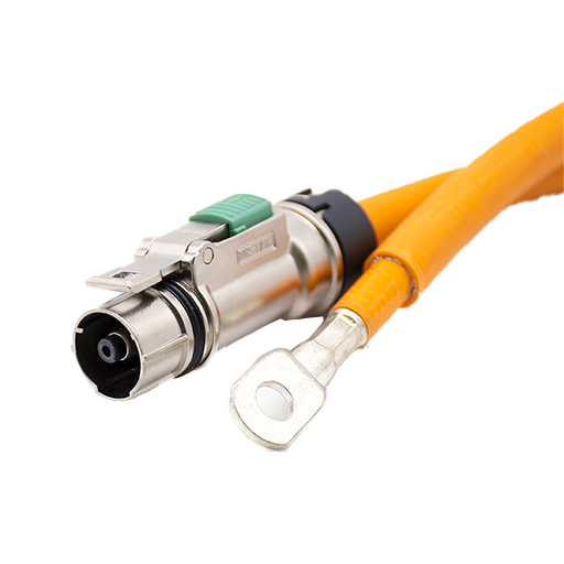
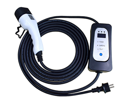
Renhotec EV Cable, crafted with top-notch conductive materials and meticulously engineered insulation, showcases outstanding impedance control and voltage-withstanding properties. Its design combines flexibility and durability to meet a wide array of installation needs. This cable is widely utilized in grid interconnections, large-scale industrial power supply systems, and high-voltage renewable energy projects, enabling smooth and efficient power transmission.
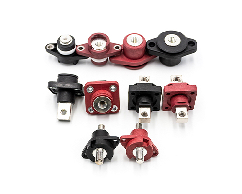
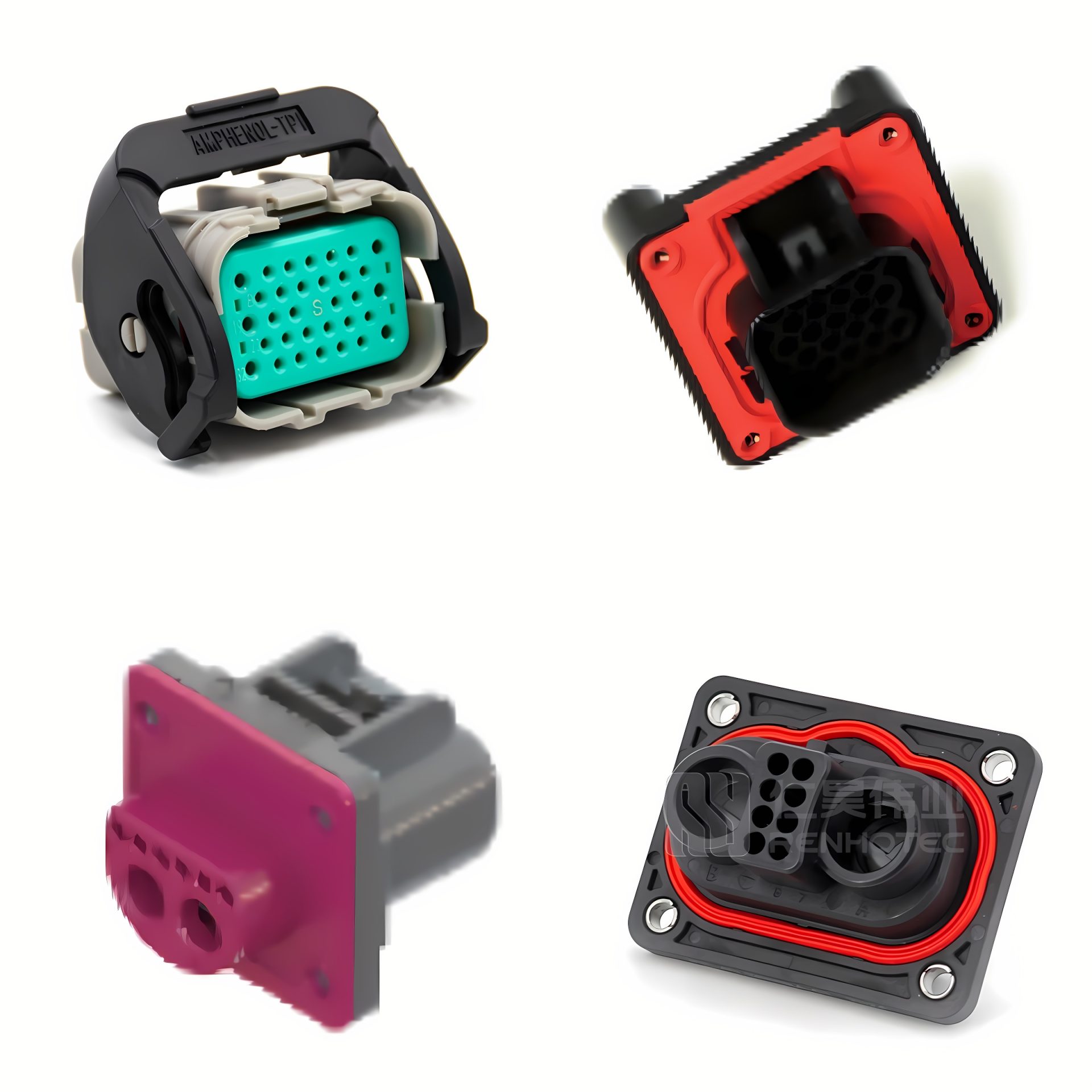
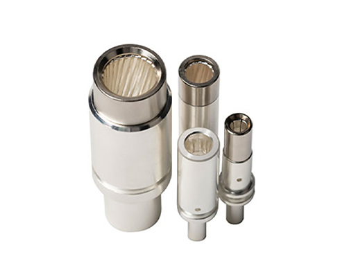
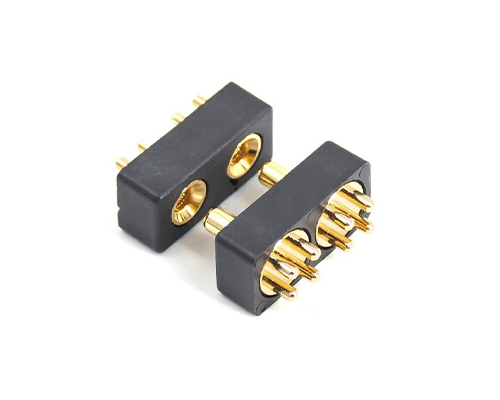
Renhotec, as a professional supplier, offers a comprehensive range of these Signal Transmission Connector products. Whether it is the high-reliability applications of the metal series or the wide adaptability of the plastic series in consumer electronic products, Renhotec can provide customers with high-quality options to meet the diverse requirements of signal transmission connections in different industries and scenarios.
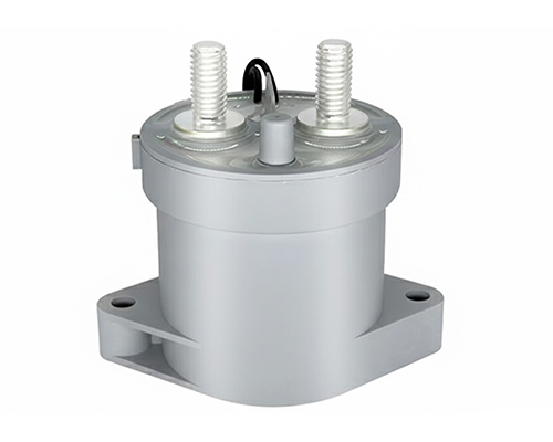
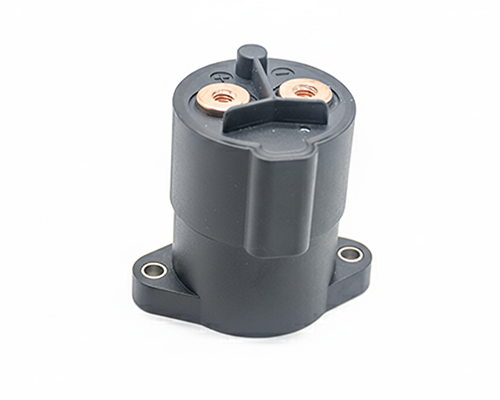
Renhotec, active in electrical components, offers High Voltage DC Contactors in Epoxy Resin Sealing and Ceramic Sealing variants, with a 20A – 1000A current range. The Epoxy Resin Sealing one is cost-effective and protective. The Ceramic Sealing variant excels in thermal stability and insulation. They’re widely used in EV charging, renewable energy grid, and industrial high-voltage DC power distribution for reliable circuit control and current interruption, providing comprehensive solutions for multiple sectors.
Why EV High Voltage Interlock (HVIL) Systems Fail: Top 7 Causes & Design Solutions
In the rapidly evolving landscape of electric vehicles (EVs) and commercial heavy-duty applications, the High Voltage Interlock Loop (HVIL) is no longer a simple safety add-on; it is a critical, complex subsystem. While theoretical designs often perform flawlessly on test benches, real-world conditions frequently expose hidden vulnerabilities.
When an HVIL system fails or triggers a false alarm, the Battery Management System (BMS) immediately disconnects the high-voltage contactors, resulting in a sudden loss of vehicle power. For electrical system engineers, addressing these issues post-production is astronomically expensive. True reliability requires moving beyond basic component selection and adopting a system-level perspective.
This article explores the top seven engineering causes of HVIL failures—ranging from software strategies and harness routing to mechanical degradation—and details the strict validation protocols required to prevent them.
1. Improper BMS Diagnostic Thresholds and Debouncing Time
Not all HVIL failures are rooted in hardware defects. The interlock circuit is typically monitored by the BMS via an Analog-to-Digital Converter (ADC) that reads voltage or PWM signals. When an EV navigates rough terrain, the physical connectors experience dynamic micro-movements that naturally cause minuscule fluctuations in contact resistance.
If the BMS software’s “debouncing time” (the delay before a signal change is registered as valid) is set too short, or if the impedance alarm threshold is overly sensitive, the software will misinterpret these normal transient fluctuations as an open circuit. This pure software diagnostic failure leads to unnecessary high-voltage shutdowns.
A vehicle’s complex electrical architecture routing. Notice the black rubber grommet (inset) designed to protect the cable as it passes through sheet metal. If such routing protections are omitted, or if the harness lacks sufficient slack, continuous vehicle vibration will cause aggressive chafing against the chassis. This mechanical wear inevitably destroys the wire insulation, shorting the HVIL circuit to the ground.
During vehicle assembly, if the low-voltage interlock harness routing lacks sufficient slack or passes through sheet metal holes without proper rubber grommets, continuous vehicle vibration will cause mechanical chafing against the chassis.
Furthermore, modern EVs frequently utilize eco-friendly, soy-based wire insulation to meet environmental regulations. This material is notoriously attractive to rodents. Whether destroyed by a rat’s teeth or worn down by metal friction, compromised insulation exposes the internal copper conductors, causing the HVIL circuit to short directly to the vehicle chassis (grounding). This unexpected physical destruction completely paralyzes the high-voltage system.
Severe physical damage on an automotive wire harness. Beyond mechanical routing chafing, modern eco-friendly soy-based insulation is highly susceptible to rodent strikes (as seen in this real case). If an HVIL circuit suffers this type of destruction, the short-to-ground will immediately trigger a system shutdown.
3. Single-Point Failures in Series Loops & Internal Component Faults
Many OEMs utilize a cost-effective global series loop, daisy-chaining the interlock wires through the Battery Pack, On-Board Charger (OBC), Power Distribution Unit (PDU), and Inverter. The critical flaw is that a single break anywhere immobilizes the entire vehicle.
Furthermore, the HVIL signal must travel inside these high-voltage components. Even if the external connectors are mated perfectly, a damaged internal micro-switch within the PDU or a cold solder joint on the internal PCBA will break the entire loop. Advanced architectures are now shifting toward parallel or zone-based interlock monitoring to isolate faults and reduce diagnostic labor.
A typical global series HVIL topology (daisy-chain). The interlock signal originates from the BMS (Tx), travels sequentially through various high-voltage components (PTC, PDU, EAC), and returns to the BMS (Rx). The critical flaw in this architecture is the single point of failure—a break at any location (such as the red X) will cause a complete loss of the return signal, unnecessarily immobilizing the entire vehicle and complicating diagnostics.
The fundamental physical logic of HVIL relies on a strict “first in, last out” mating sequence to prevent arcing. Failures frequently occur when tolerance stack-ups in the mechanical housing shorten this critical wipe length, erasing the timing delay. Additionally, when assembly line workers perform “blind mating” in cramped spaces, improper angles can bend delicate signal pins or cause pin push-out.
Superior mechanical design mandates a Connector Position Assurance (CPA) lock. More importantly, manufacturers must validate these designs through Insert and Withdraw Force and Connector Retention Force Testing. These empirical tests ensure that mating forces are ergonomic and that terminal locks will not deform or fail, even under abusive assembly conditions. (For further reading, refer to our guide: High Voltage Connector Design: 7 Types of the Contact Structure).
To ensure flawless manual assembly on the production line and prevent mechanical damage to internal HVIL terminals, connectors undergo rigorous insertion and withdrawal force testing at a controlled speed of 25 mm/min. As demonstrated in the empirical data table, both the mating and un-mating forces across multiple cycles remain consistently well below the strict 100 N threshold. This optimal force profile guarantees secure locking while preventing terminal deformation that could lead to long-term impedance issues.
5. Micro-Fretting Under High-Frequency Vibration
Commercial EVs subject connectors to relentless, high-frequency vibrations. These vibrations induce micro-fretting—microscopic sliding movements between the mated HVIL contact surfaces that wear away the protective conductive plating and expose the base metal to oxidation. This oxide layer causes contact resistance to spike intermittently.
Mitigating this requires robust terminal spring designs engineered for realistic lifespans, such as a standard 100 to 500 mating cycles for internal pack connectors. Relying on comprehensive Contact Resistance & Mating Cycle Test is non-negotiable. This protocol tracks impedance fluctuations dynamically during durability cycling, guaranteeing the resistance remains stable long after the vehicle leaves the factory.
Contact Resistance Verification and Test Data.(Fig. 1 & 2) The test setup and precision meter tracking for measuring contact resistance. (Table) Empirical results from samples 1# to 3#, demonstrating that after subtracting the cable resistance (0.03 mΩ), the actual contact resistance ranges consistently between 0.15 mΩ and 0.16 mΩ – significantly lower than the strict ≤ 0.40 mΩ engineering requirement. This stable, low-impedance profile prevents the micro-fretting voltage drops that typically trigger false BMS alarms.Comprehensive Empirical Validation Framework for HVIL Connectors (Conforming to SAE J1742 Test Methodologies). To ensure high field reliability and prevent the failure modes discussed above, components undergo a rigorous, multi-stage testing sequence. (Fig. 1) Deep water immersion (1-meter depth for 30 mins) immediately following 100 mechanical mating cycles to verify housing and seal integrity under stress. (Fig. 2) High-precision contact resistance tracking to ensure post-durability impedance remains well below the 0.40 mΩ limit, preventing BMS false alarms caused by micro-fretting. (Fig. 3) Dielectric strength (withstand voltage) testing applying 4800V DC to ensure no breakdown occurs under extreme electrical stress. (Fig. 4) Insulation resistance verification using 500VDC to prevent leakage currents. This holistic testing methodology ensures robust performance in the harshest EV operating environments.
6. Seal Degradation & Insulation Failure Under Environmental Extremes
Connectors endure brutal thermal shocks, often cycling from -40°C to +125°C near battery packs. These extremes cause elastomeric seals to experience compression set, permanently losing elasticity. Once a seal degrades, moisture and road salts ingress, creating micro-shorts between the HVIL pins and high-voltage terminals.
An IP67 rating is meaningless if it only applies to a new component. True validation requires executing Thermal Aging and Temperature Rise Test to expose components to prolonged heat before dielectric testing. Furthermore, Drop Test simulates assembly impacts, while Salt Spray Test ensures the plating and housings resist severe corrosion over years of exposure.
Temperature Rise and Thermal Stability Verification. To evaluate the thermal behavior of the high-voltage connector under heavy load conditions, a comprehensive temperature rise test is conducted using a programmable DC source and a multichannel data logger. As illustrated in the thermal monitoring setup and the resulting Temperature Rise Curve, temperatures across critical contact points—such as the receptacle copper bar (CH001), plug crimping area (CH003), cable insulation (CH004), and lug crimping area (CH006)—stabilize well within safe operating limits over an extended testing duration. This exceptional thermal performance ensures that high operating currents will not induce excessive thermal aging, contact degradation, or impedance spikes in real-world EV applications.Corrosion Resistance Verification via Salt Spray Testing. To ensure long-term reliability in harsh coastal or winter environments where road de-icing salts are prevalent, high-voltage connectors undergo rigorous salt spray testing. The precision salt spray chamber and digital control panel maintain strict environmental parameters (such as continuous salt fog exposure and controlled temperature). Post-test inspections of the plug and receptacle assemblies confirm that the robust surface plating and sealing design effectively prevent galvanic corrosion and oxidation, ensuring that the connector housing and internal locking mechanisms remain fully functional without degradation.
7. Electromagnetic Interference (EMI) in High-Power Environments
EV architectures route high-voltage cables in close proximity to the low-voltage HVIL wires. When traction inverters switch currents at high frequencies, they generate massive transient electromagnetic fields. If the HVIL circuit lacks adequate shielding, these fields induce noise currents, which the BMS may erroneously interpret as a physical disconnection. Connectors must feature continuous 360-degree shielding from the cable braid through the shell to the equipment chassis. Optimized grounding paths provide a low-impedance route for high-frequency noise, keeping the delicate HVIL signal pristine.
The High Voltage Interlock Loop is a highly critical safety architecture operating at the intersection of software logic, system routing, and electromechanical engineering. Preventing failures requires a holistic approach—from optimizing BMS debouncing times to demanding empirical testing data for physical components. By understanding these seven failure modes, engineers can build robust architectures that keep vehicles safe in the most demanding conditions.
(For detailed test reports, mechanical life data, or engineering consultation regarding your specific EV architecture, contact our sales engineering team to review your schematics.)
Let us know how we can help?
We look forward to hearing from you! We will respond within 24 hours.