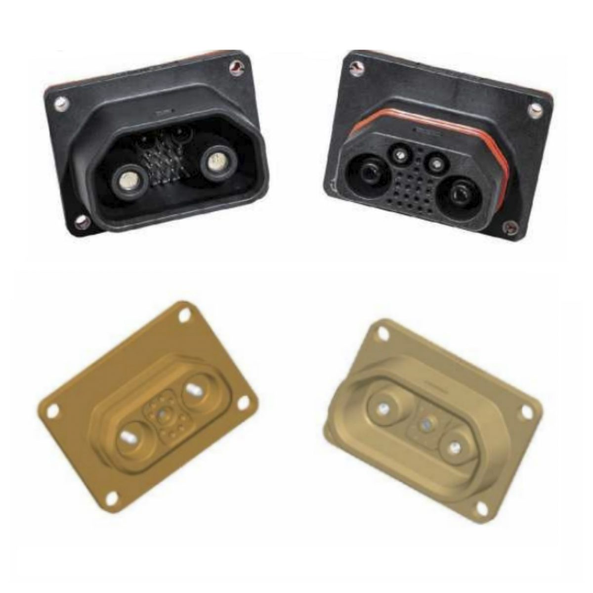
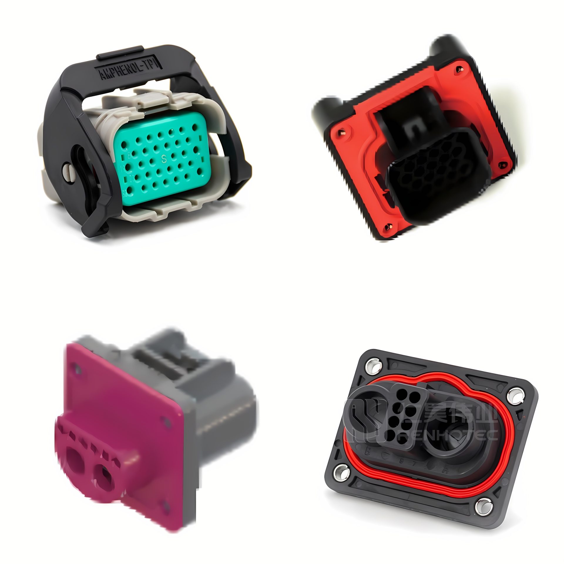
The Rectangular Connector is widely used in aerospace, medical instruments, consumer electronics (such as computers, TVs, game consoles, etc.), industrial control equipment, communication equipment, and automotive electronics. With its reliable connection performance, diverse specifications, and relatively convenient plug-in and unplug operations, it has become an indispensable component in various electronic and electrical applications.
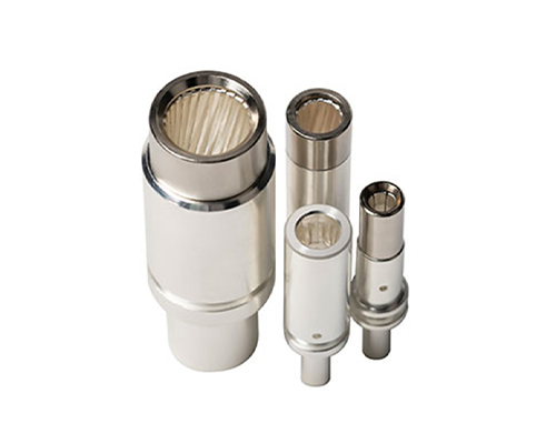
J30J Connectors and Cable Assemblies
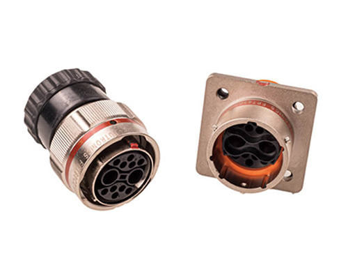
J14 Connectors and Cable Assemblies
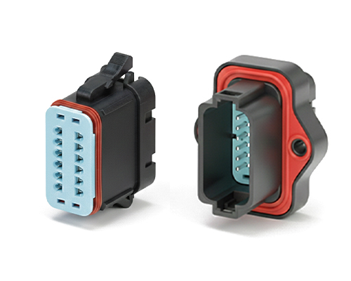
J36A Connectors and Cable Assemblies

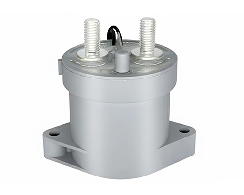
M80 Connectors
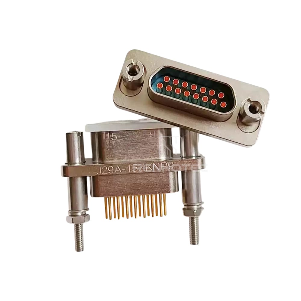
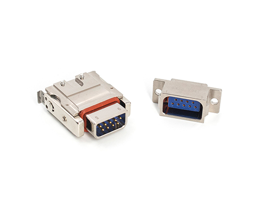
J29A Connectors and Cable Assemblies