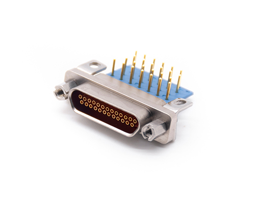
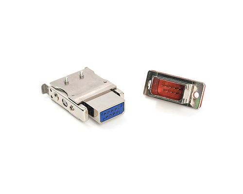
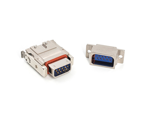
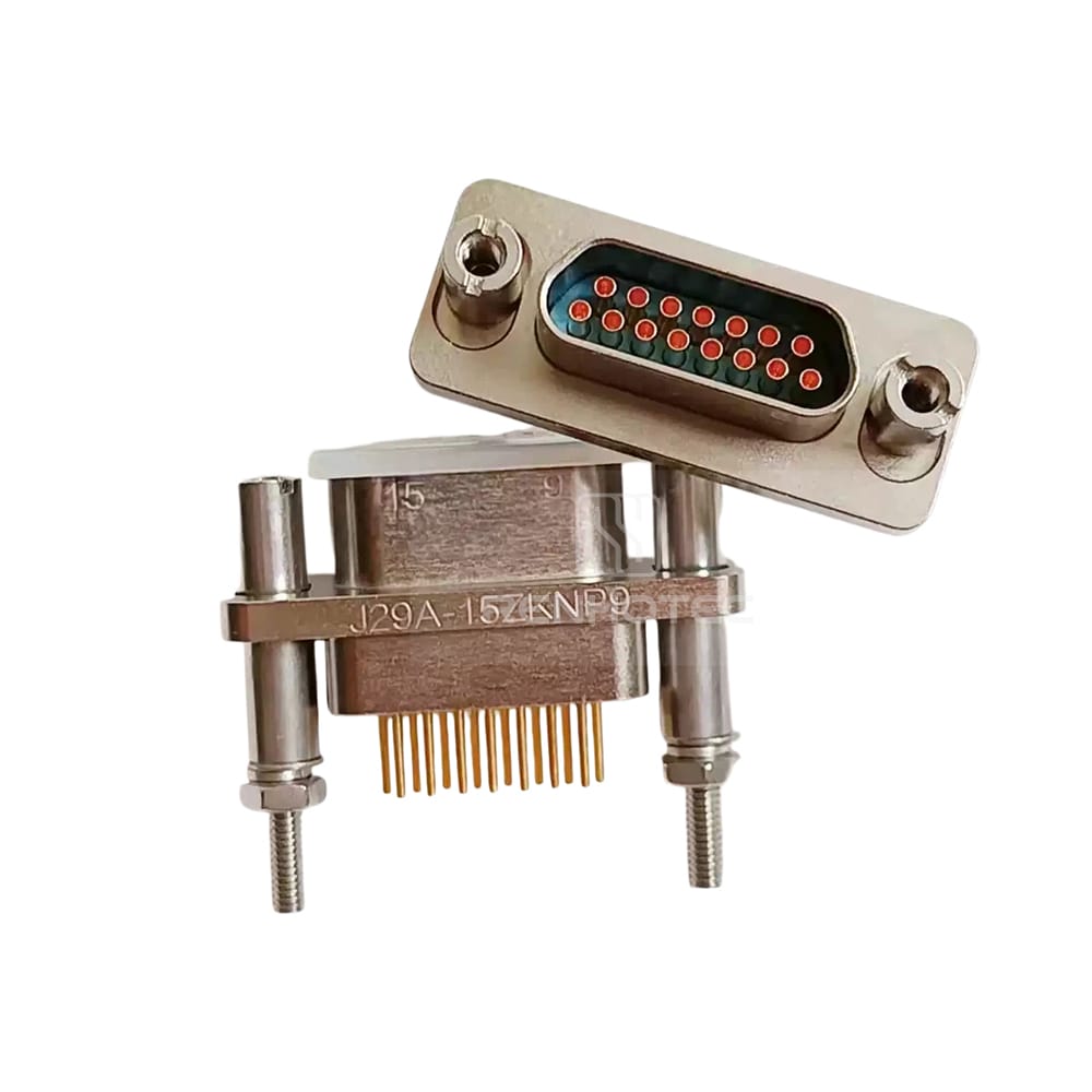
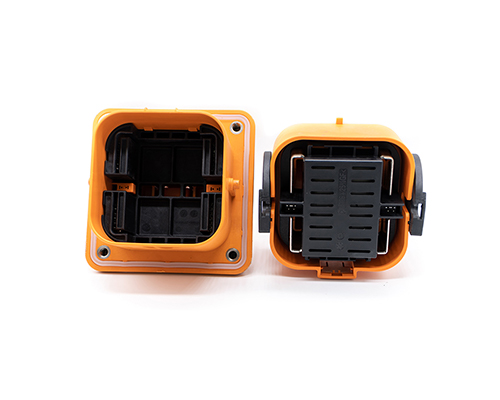
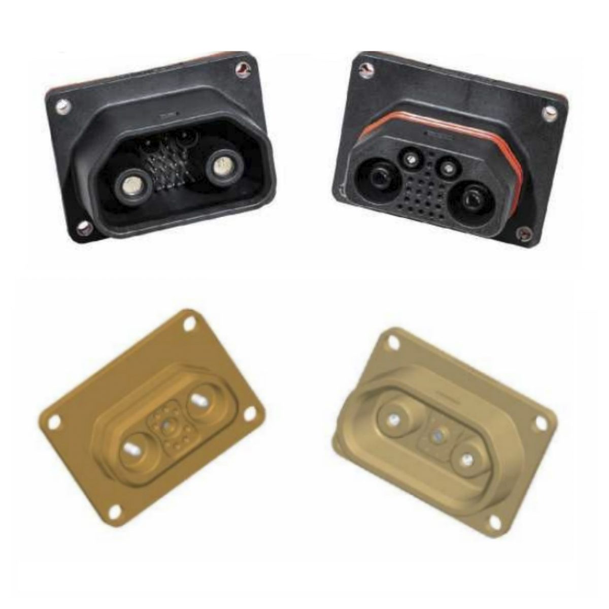
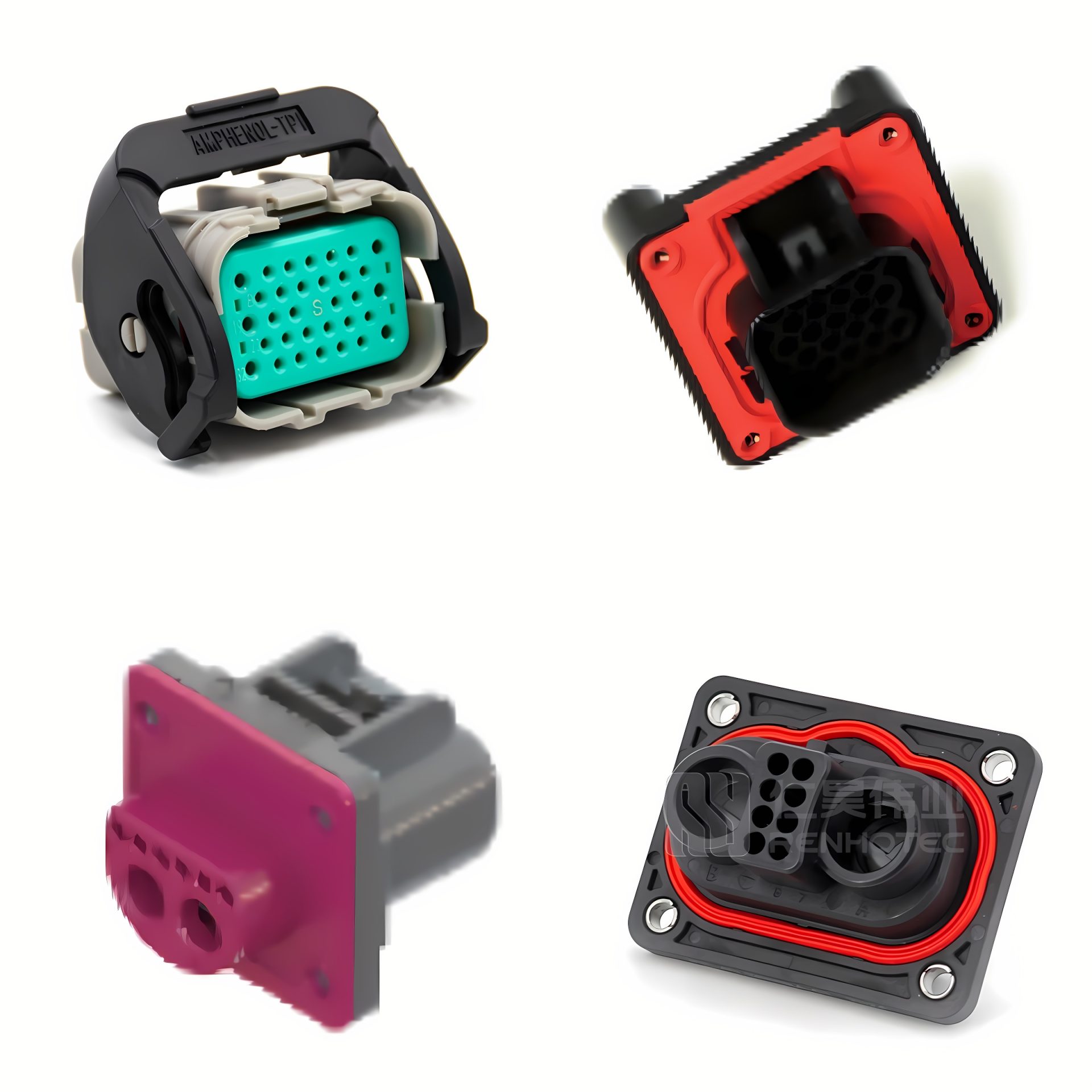
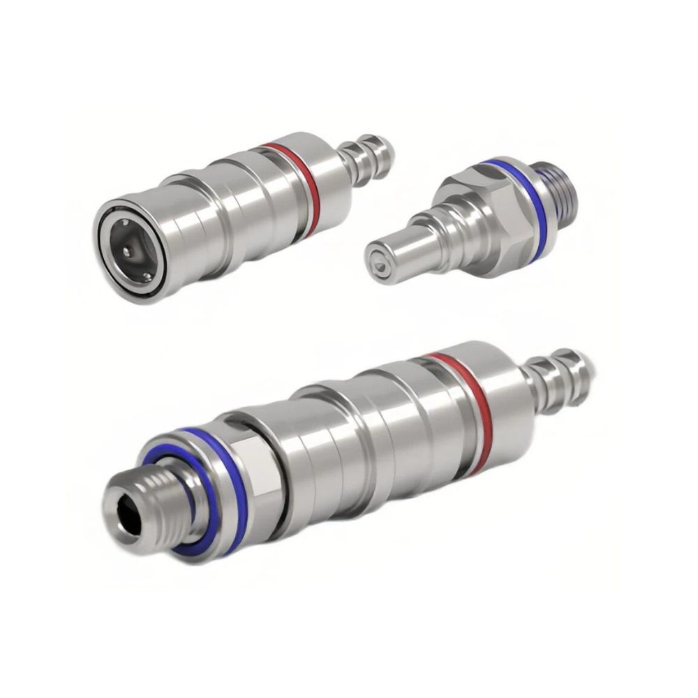
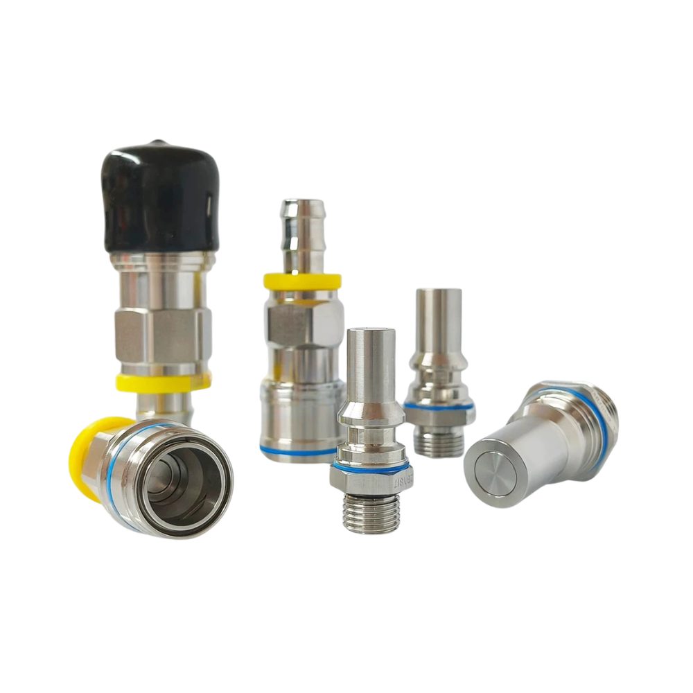
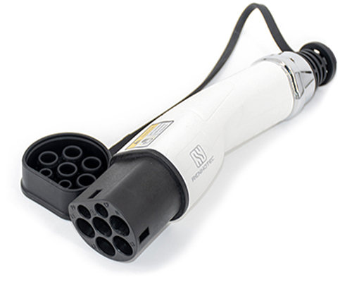
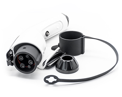
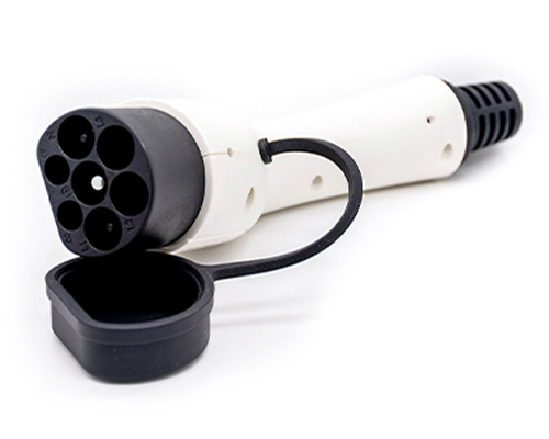
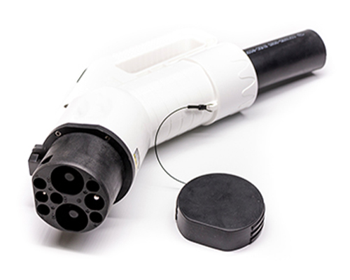
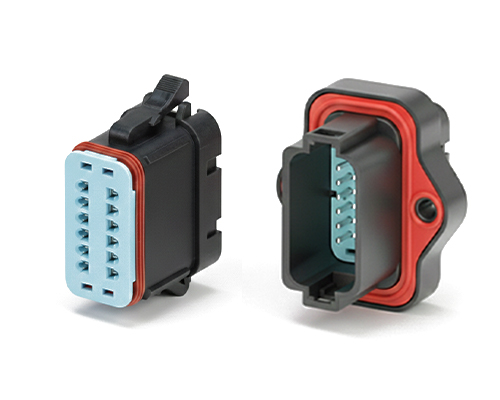
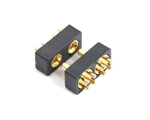
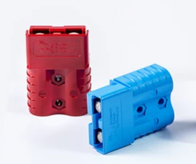
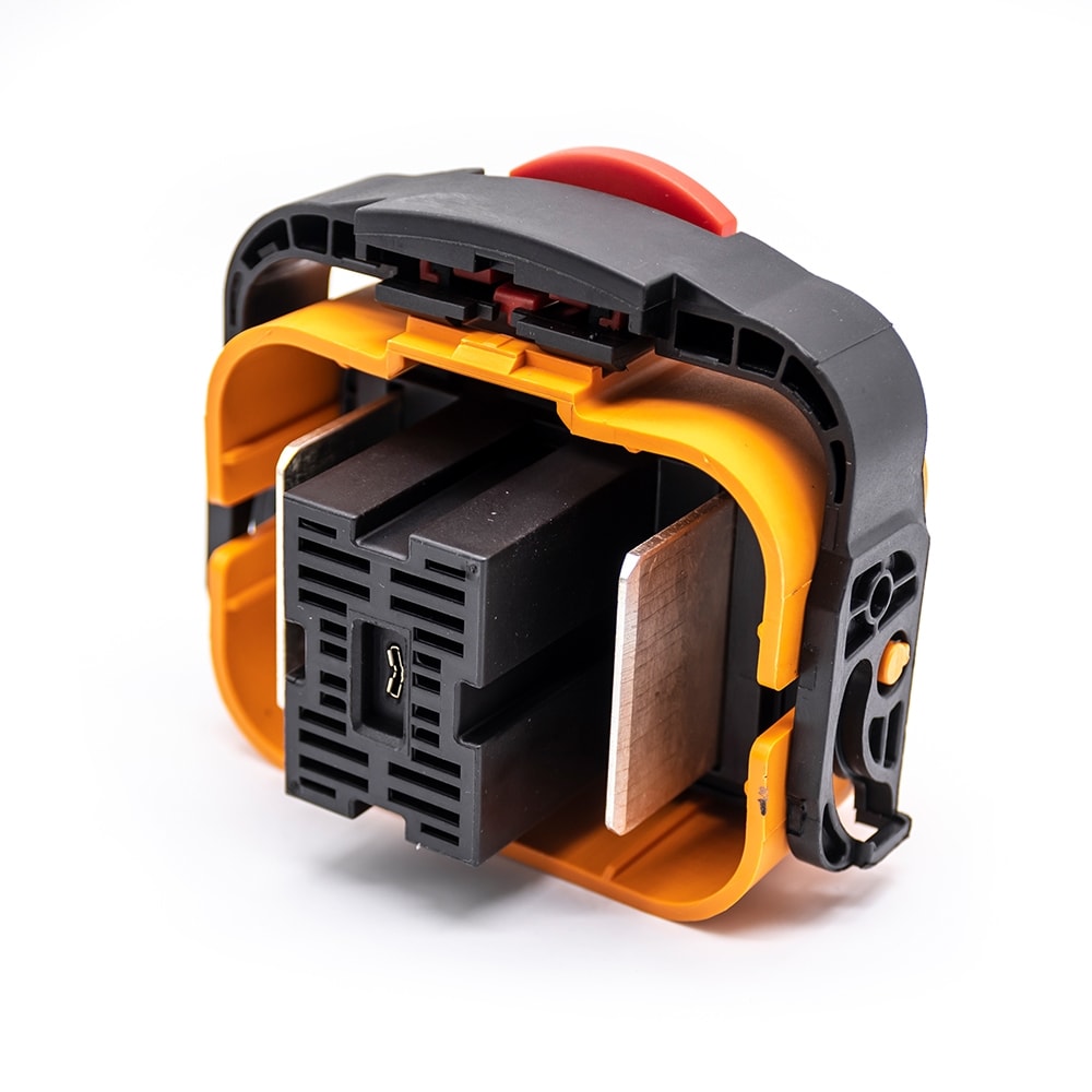
The Rectangular Connector is widely used in aerospace, medical instruments, consumer electronics (such as computers, TVs, game consoles, etc.), industrial control equipment, communication equipment, and automotive electronics. With its reliable connection performance, diverse specifications, and relatively convenient plug-in and unplug operations, it has become an indispensable component in various electronic and electrical applications.
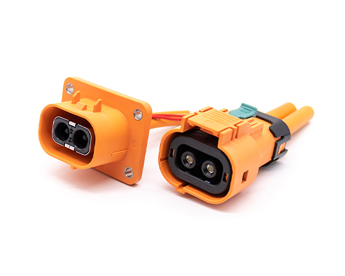
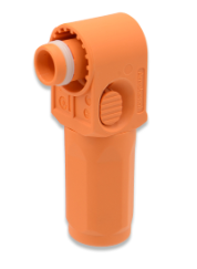
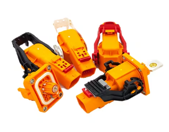
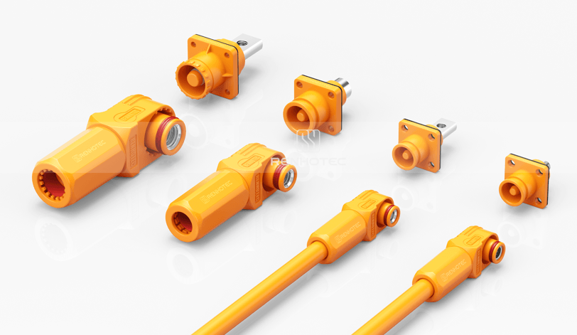
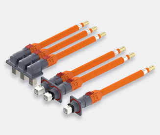
High Voltage Connectors are widely used in EV power systems, renewable energy installations, and industrial high-voltage circuits. Renhotec’s series drives the building of efficient, safe, and sustainable electrical ecosystems, meeting current technological demands.
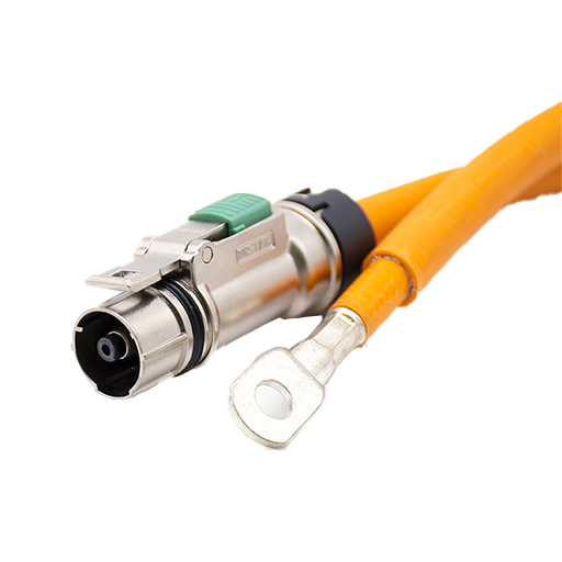
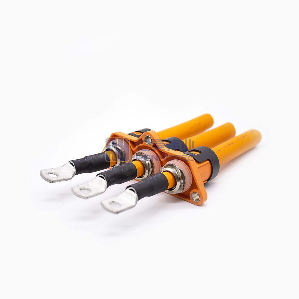
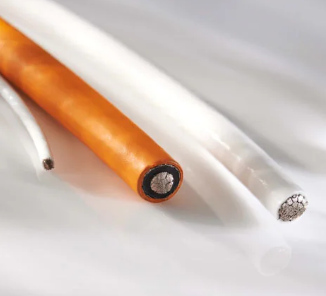
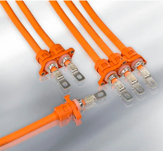
Renhotec EV Cable, crafted with top-notch conductive materials and meticulously engineered insulation, showcases outstanding impedance control and voltage-withstanding properties. Its design combines flexibility and durability to meet a wide array of installation needs. This cable is widely utilized in grid interconnections, large-scale industrial power supply systems, and high-voltage renewable energy projects, enabling smooth and efficient power transmission.
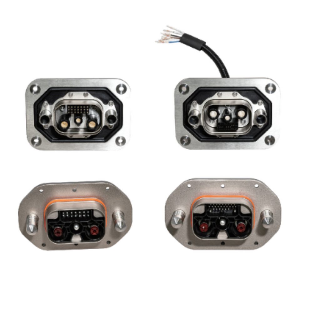
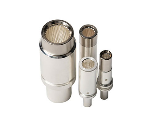
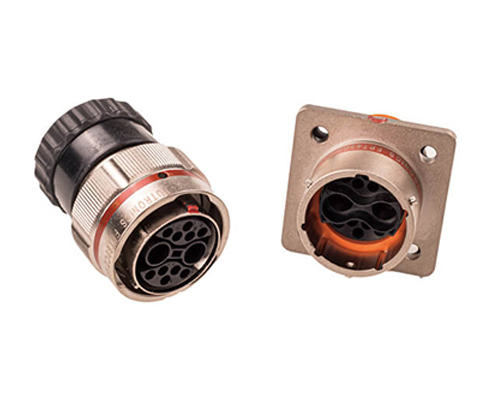
Renhotec, as a professional supplier, offers a comprehensive range of these Signal Transmission Connector products. Whether it is the high-reliability applications of the metal series or the wide adaptability of the plastic series in consumer electronic products, Renhotec can provide customers with high-quality options to meet the diverse requirements of signal transmission connections in different industries and scenarios.
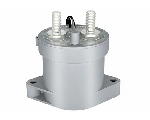
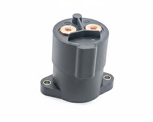
Renhotec, active in electrical components, offers High Voltage DC Contactors in Epoxy Resin Sealing and Ceramic Sealing variants, with a 20A – 1000A current range. The Epoxy Resin Sealing one is cost-effective and protective. The Ceramic Sealing variant excels in thermal stability and insulation. They’re widely used in EV charging, renewable energy grid, and industrial high-voltage DC power distribution for reliable circuit control and current interruption, providing comprehensive solutions for multiple sectors.
8 Most Common High Current Connector Types Used in Battery Energy Storage Systems (BESS)
Battery energy storage systems (BESS) rely on high current connectors to safely transfer DC power between battery modules, battery racks, power conversion systems (PCS), and other electrical equipment. Unlike standard electrical connectors, BESS connectors are designed to handle higher current, higher voltage, and demanding operating environments while ensuring reliable and safe power transmission. This guide explores the eight most common high current connector types used in BESS, their typical applications, key features, and selection considerations to help engineers and system integrators choose the right solution.
How to Select the Right High Current Connector for BESS
When selecting a high current connector for BESS, consider more than just the current rating. The right connector should match your system voltage, installation method, operating environment, and maintenance requirements.
Key factors include:
Current and voltage rating (up to 1500V DC for many BESS applications)
Connection method (plug-in or bolt-on)
IP protection for indoor or outdoor use
Safety features, such as touch-safe design and HVIL
Maintenance frequency and ease of replacement
Choosing the right connector improves system reliability, simplifies maintenance, and supports long-term operation.
Overview: Common High Current Connector Types in BESS
Connector Type
Typical Application
Main Features
Single-pole Plug & Socket Connector
Battery rack, battery module, DC connection
Quick connection, high current capability, compact design
Panel Mount Receptacle / Feed-through Connector
Battery cabinet, PCS, enclosure interface
Fixed installation, safe external connection
Busbar Terminal / Bolt-on Connector
Battery rack, power distribution
High reliability, low resistance, permanent connection
Battery Pole Connector
Modular battery systems
Touch-safe, fast installation, modular design
High Current Jumper Cable Connector
Rack-to-rack or internal power connection
Flexible cable connection, easy maintenance
Quick Disconnect Power Connector
Industrial energy storage systems
Fast mating and frequent connection cycles
HVIL-enabled Power Connector
High voltage BESS applications
Adds safety interlock function
Busbar Interface Connector
Battery modules and power distribution systems
Direct busbar connection, space saving
Mainstream Power Connection Solutions for BESS – Types 1 to Type 3
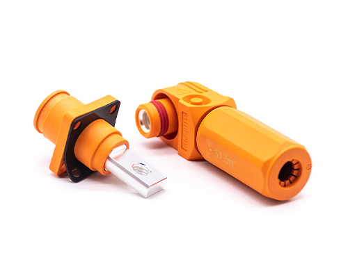
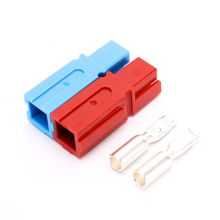
Single-pole plug and socket connectors are one of the most widely used high current connectors in BESS applications. They are commonly used for connecting battery racks, battery modules, DC distribution units, and power conversion systems.
Unlike traditional multi-pin connectors, single-pole connectors separate positive and negative power paths into individual connectors. This design allows manufacturers to optimize the contact structure for high current transmission while maintaining a compact size.
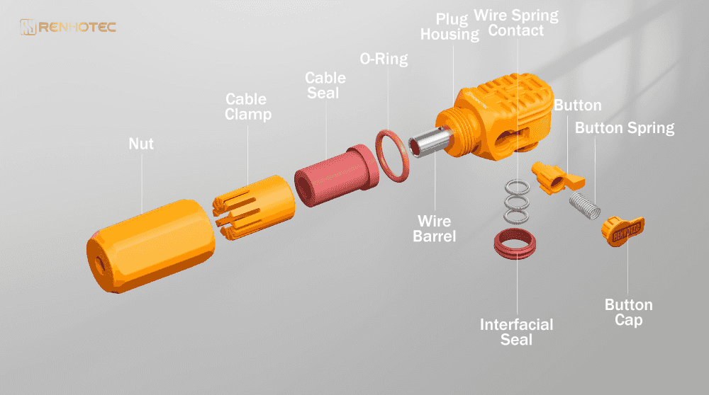
Typical single-pole BESS connectors consist of:
Plug and receptacle housing
High current contact system
Cable termination area
Mechanical locking mechanism
Touch-safe protection structure
Many modern designs use spring-based contact technologies, such as RADSOK-type contacts, to increase the effective conductive area and reduce electrical resistance.
For example, Amphenol SurLok Plus uses RADSOK technology and provides single-pole high power connection solutions with options including crimp, screw, and busbar termination.
Electrical Parameters
Typical specifications include:
Voltage Rating
1000V DC | 1500V DC
Current Rating
50A | 100A | 200A | 350A | 500A
Protection Level
IP67 | IP6K9K
Temperature Range
Approximately -40°C to +125°C
Actual performance depends on cable size, installation method, ambient temperature, and thermal management design.
Typical Applications
Single-pole plug and socket connectors are commonly used in:
Battery rack power connections
Battery module connections
DC input/output connections
PCS connections
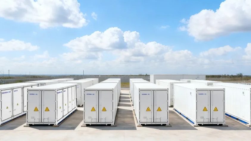
Energy storage container systems
For example, in a containerized BESS, these connectors may be installed between battery racks and DC bus systems, allowing faster installation and easier maintenance compared with traditional bolted connections.
Advantages
The main advantages include:
1.Fast Installation Compared with traditional screw terminals, plug-in connectors significantly reduce installation time.
2. High Current Capability Dedicated high current contacts allow these connectors to support hundreds of amps in a compact structure.
3. Easy Maintenance Technicians can disconnect and replace battery units without removing multiple cable terminals.
4. Improved Safety Many products include touch-proof designs, mechanical keying, or HVIL options to reduce the risk of incorrect connection or accidental contact.
Limitations and Product Considerations
Although single-pole connectors offer excellent flexibility, they also have some limitations:
Higher cost compared with simple bolt connections
Require compatible plug and receptacle pairs
Mechanical locking components may require inspection after long-term use
Current capacity depends heavily on thermal conditions
For large-scale stationary energy storage projects where connections are rarely disconnected, some designers may still prefer busbar or bolt-on solutions.
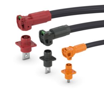
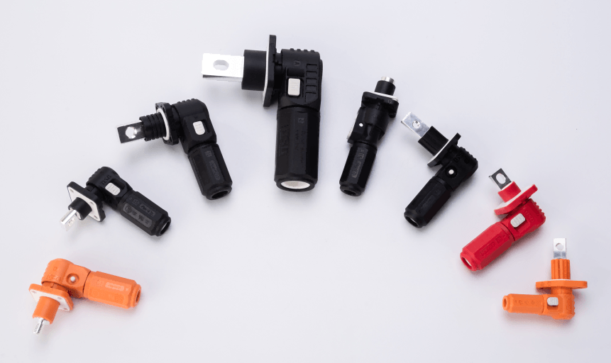
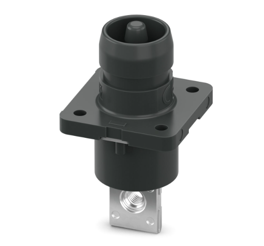
Battery pole connectors are specially designed for modular battery energy storage systems. They provide a safer and faster alternative to traditional cable lug connections between battery modules.
Unlike standard terminal connections, battery pole connectors combine the advantages of:
High current transmission
Plug-in installation
Touch-safe protection
Mechanical coding
Flexible cable routing
These connectors are commonly used in modular BESS designs where battery units need to be installed, replaced, or expanded efficiently.
For example, Phoenix Contact battery pole connectors are designed for ESS applications with up to 1500V DC and 350A capability, supporting modular battery connections with IP67 protection and touch-safe construction.
Typical design features include:
Single-pole structure
Polarization protection
Locking mechanism
Rotatable cable connection
High-current contact system
The ability to rotate the cable direction is particularly useful in compact battery cabinets where installation space is limited.
Electrical Parameters
Typical specifications include:
Voltage Rating
1000V DC | 1500V DC
Current Rating
120A | 200A | 250A | 350A
Protection Level
IP67
Mating Cycles
50 – 100
Typical Applications
Battery pole connectors are commonly found in:
Battery module connections
Battery rack assemblies
Industrial BESS systems
Utility-scale energy storage containers
They are especially suitable for modular battery architectures because individual battery units can be disconnected without completely removing the entire power connection system.
Advantages
1. Improved Installation Safety Compared with exposed cable lugs, touch-safe battery pole connectors reduce the risk of accidental contact with high-voltage DC terminals.
2. Faster Assembly Plug-and-play connection reduces installation time during manufacturing and field deployment.
3. Flexible System Design The connector structure allows easier battery expansion and maintenance.
Limitations
Potential limitations include:
Higher cost than traditional bolt connections
Requires matched connector pairs
Lower suitability for extremely high current applications requiring direct busbar connections
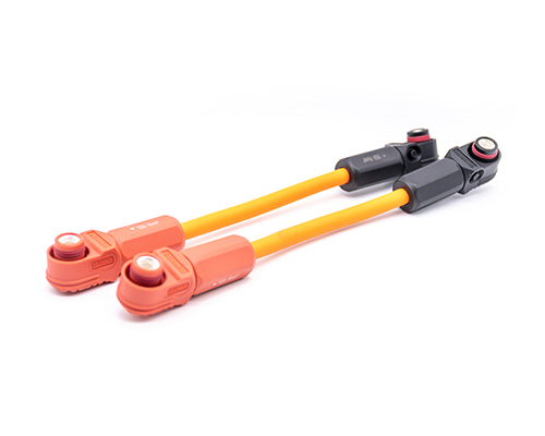
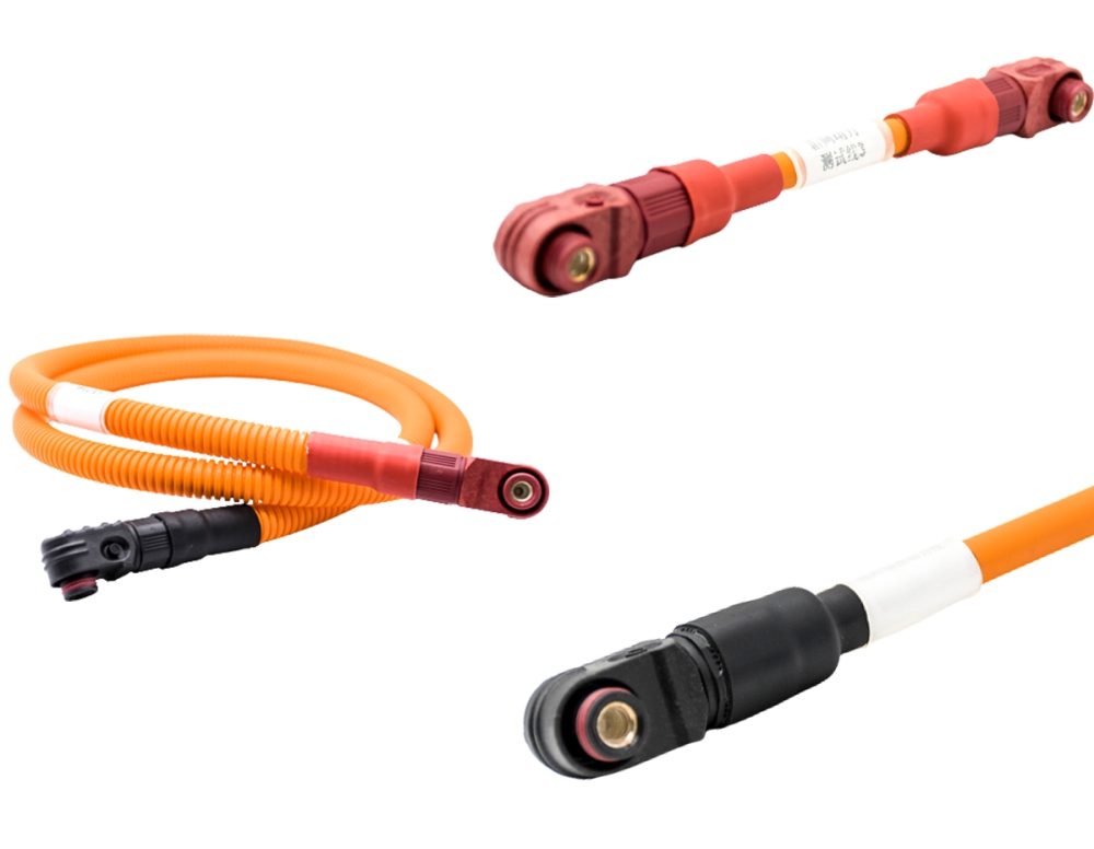
High current jumper cable connectors combine high current connectors with pre-assembled power cables. They are widely used when flexible connections are required between battery racks, modules, and power distribution units.
A typical jumper cable assembly includes:
Two high current connectors
Flexible power cable
Crimped contacts
Protective insulation
Compared with rigid busbar connections, jumper cables provide better installation flexibility and can absorb mechanical tolerance between different system components.
Electrical Parameters
Typical specifications:
Voltage
600V DC | 1000V DC | 1500V DC
Current
100A | 200A | 300A | 500A
Cable Size
25mm² | 35mm² | 50mm² | 70mm² | 95mm²
Typical Applications
Common applications include:
Battery rack interconnection
Battery cabinet internal wiring
PCS connection
DC distribution connection
In containerized BESS systems, jumper cable assemblies are often preferred because they simplify installation and allow easier routing inside limited spaces.
Advantages
Flexible Installation Cable assemblies can adapt to different mechanical layouts.
Easier Maintenance Technicians can replace complete cable assemblies instead of repairing individual terminals.
Reduced Installation Errors Pre-assembled cables reduce wiring mistakes during installation.
Limitations
Cable length and bending radius must be carefully considered
Higher cost compared with simple busbar connections
Heat dissipation depends on cable size and installation environment
System Integration Connection Solutions – Type 4 to Type 5
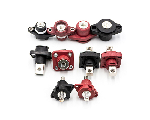
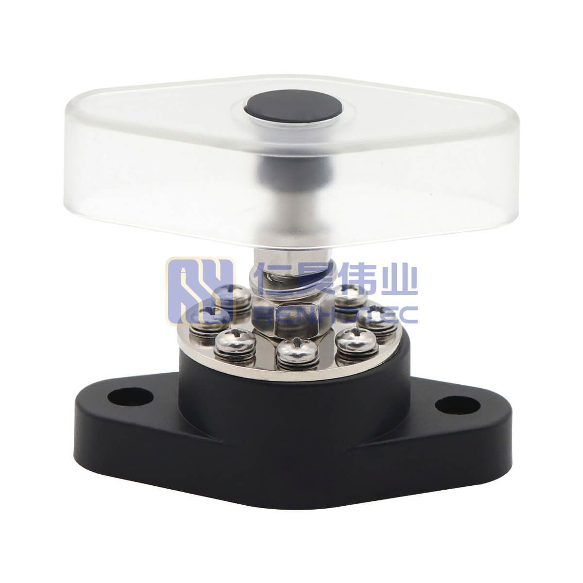
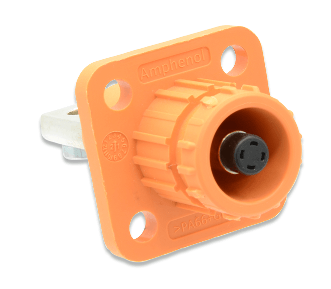
Panel mount receptacles, also known as feed-through connectors, are another important type of battery energy storage connector used in BESS.
Unlike cable-to-cable connectors, panel mount connectors are fixed directly onto equipment housings, such as:
Battery cabinets
Energy storage containers
PCS enclosures
DC distribution cabinets
The connector provides an external interface between internal electrical components and external power cables.
A typical design includes:
Panel mounting flange
Fixed receptacle housing
High current contact
Internal busbar or cable termination
Environmental sealing structure
This design allows manufacturers to create a clean and standardized interface between different system components.
Electrical Parameters
Typical ratings include:
Voltage
600V DC | 1000V DC | 1500V DC
Current
100A | 200A | 300A | 500A+
Protection
IP65 | IP67
Typical Applications
Panel mount connectors are widely used in:
Battery energy storage cabinets
Outdoor BESS containers
PCS cabinets
DC combiner boxes
Charging and power conversion systems
For example, a battery cabinet may use panel mount receptacles on the external side, allowing installers to quickly connect power cables without opening the internal electrical compartment.
Advantages
1. Standardized System Interface Panel connectors simplify system integration by creating fixed connection points.
2. Improved Protection Because the connection point is sealed on the enclosure, it helps maintain: dust protection, water resistance, and electrical safety.
3. Easier Installation External cable connection becomes faster during system assembly and maintenance.
Limitations
Potential limitations include:
Larger installation space requirement
Higher mechanical design requirements for enclosure mounting
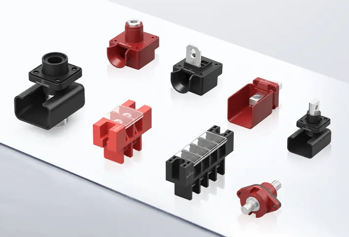
Busbar interface connectors provide a direct connection between the connector and the internal copper busbar system.
They combine some advantages of traditional busbar connections and plug-in connectors:
High current capability
Compact installation
Faster assembly
Unlike standard cable connectors, busbar interface connectors are mainly designed for integration inside battery modules, racks, and power distribution systems.
Electrical Parameters
Typical specifications:
Voltage
1000V DC | 1500V DC
Current
150A | 250A | 350A | 500A+
Typical Applications
Common applications include:
Battery modules
Battery racks
DC distribution units
Energy storage cabinets
Advantages
Compact Design Direct busbar connection saves installation space.
High Reliability Short current path reduces electrical losses.
Efficient Manufacturing Suitable for standardized battery production.
Limitations
Requires precise mechanical design
Less flexible after installation
Mainly suitable for integrated systems
Specialized BESS Connection Solutions – Type 6 to Type 8
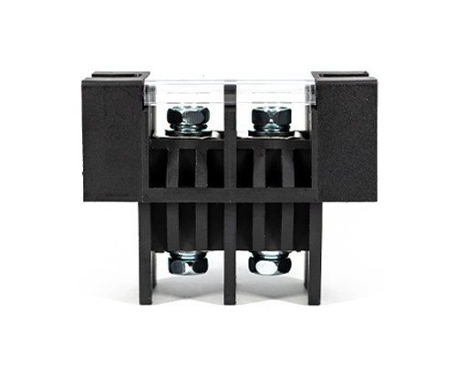
Busbar and bolt-on connections remain one of the most common connection methods in large-scale BESS installations.
Unlike plug-in connectors, bolt-on connectors create a direct mechanical and electrical connection through:
Copper or aluminum busbars
Bolted terminals
Compression contacts
Conductive plates
This type of connection is especially common in stationary energy storage systems where high reliability and low electrical resistance are more important than frequent disconnect capability.
Electrical Parameters
Typical characteristics:
Voltage
1000V DC | 1500V DC
Current
Several hundred amps | Thousands of amps in large systems
High Voltage Interlock Loop (HVIL) enabled connectors integrate a safety signal circuit into the main power connector.
The purpose of HVIL is to detect whether a high-voltage connection is properly engaged or disconnected.
In BESS applications, HVIL helps prevent unsafe situations by ensuring that:
The power system is shut down before connector separation
Operators cannot accidentally disconnect live high-voltage circuits
The system can monitor connector status
HVIL connectors are becoming more common in higher voltage battery systems, especially where safety requirements are strict.
Electrical Parameters
Typical specifications:
Voltage
1000V DC | 1500V DC
Current
100A – 500A
Additional low-voltage signal contacts are included for interlock monitoring.
Typical Applications
Used in:
High voltage battery cabinets
Utility-scale BESS
EV charging energy storage systems
Industrial battery systems
Advantages
Enhanced Safety Provides active monitoring of connector status.
System Integration Can communicate connector conditions with BMS and control systems.
Limitations
More complex structure
Higher cost
Requires system-level HVIL design
Conclusion
High current connectors are essential components in battery energy storage systems. As BESS designs continue to evolve toward higher voltage, larger capacity, and more modular architectures, connector selection has become increasingly important.
The most suitable connector depends on several factors, including:
Required current capacity
System voltage
Installation environment
Maintenance frequency
Safety requirements
Space limitations
For modular battery systems, plug-in solutions such as single-pole connectors and battery pole connectors provide fast installation and easy maintenance. For large fixed installations, busbar and bolt-on solutions remain popular due to their high reliability and low electrical resistance.
Understanding the different BESS connector types helps engineers and system integrators select the right connection solution for their energy storage projects.

 Deutsch